Liquid crystal display screen capable of automatically controlling temperature

A liquid crystal display, current temperature technology, applied in the direction of nonlinear optics, instruments, optics, etc., can solve problems such as drop, achieve the effect of expanding the application range, improving the service life, and increasing the working temperature

Inactive Publication Date: 2017-06-13
HEFEI MINZHONGYIXING SOFTWARE DEV CO LTD
View PDF1 Cites 6 Cited by
  • Summary
  • Abstract
  • Description
  • Claims
  • Application Information

AI Technical Summary

Benefits of technology

This patented technical effect describes a new type of liquid crystalline displays (LCD) device called Liquid Crystaled Display (LCDI). These devices have several benefits such as automatic controllability over temperatures without requiring external equipment like fans or coolants for better functioning at very cold conditions. They also allow for continuous and uniform distribution of warmth during normal operating hours while maintaining their functionality after being warmed down due to excessively hotter ambient temperatures. Additionally, they provide improved reliance upon battery sources because there're less likely any issues related to batteries themselves. Overall, these improvements improve overall efficiency and lifespan of LCDI devices.

Problems solved by technology

This patented technical problem addressed in this patents relates to improving the efficiency at controlling the temperatures used during operation of liquid Crystals Display (LCD).

Method used


Image

  • Liquid crystal display screen capable of automatically controlling temperature
  • Liquid crystal display screen capable of automatically controlling temperature

Examples


Embodiment 1

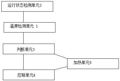
[0061] combine figure 1 , figure 2 , a liquid crystal display that can automatically control the temperature provided in this embodiment, a temperature detection unit 1, used to detect the current temperature of the liquid crystal display;

[0062] The running state detection unit 2 is used to detect whether the liquid crystal display is in the running state;

[0063] The judging unit 3 is used to judge whether the current temperature of the liquid crystal display screen detected by the temperature detection unit 1 is lower than or equal to a preset temperature threshold according to the result that the liquid crystal display screen output by the running state detection unit 2 is in the running state, and The judgment result is sent to the control unit 4;

[0064] The control unit 4, after receiving the temperature judgment result sent by the judgment unit 3, the control unit 4 controls the heating unit 5 to start heating, and after the heating unit 5 performs the heating acti

Embodiment 2

[0081] combine figure 1 , figure 2 , a liquid crystal display that can automatically control the temperature provided in this embodiment, a temperature detection unit 1, used to detect the current temperature of the liquid crystal display;

[0082] The running state detection unit 2 is used to detect whether the liquid crystal display is in the running state;

[0083] The judging unit 3 is used to judge whether the current temperature of the liquid crystal display screen detected by the temperature detection unit 1 is lower than or equal to a preset temperature threshold according to the result that the liquid crystal display screen output by the running state detection unit 2 is in the running state, and The judgment result is sent to the control unit 4;

[0084] The control unit 4, after receiving the temperature judgment result sent by the judgment unit 3, the control unit 4 controls the heating unit 5 to start heating, and after the heating unit 5 performs the heating acti


PUM


Abstract

The invention belongs to the technical field of computer hardware designs and provides a liquid crystal display screen capable of automatically controlling the temperature. The liquid crystal display screen comprises a temperature detection unit, an operation state detection unit, a judgment unit and a control unit, wherein the control unit is used for receiving a temperature judgment result sent by the judgment unit and then controlling a heating unit to heat; and after the heating unit executes heating actions, the heating unit is controlled to stop heating according to a judgment result that a current temperature of the crystal display screen is higher than that a pre-set temperature threshold judged by the judgment unit. According to the liquid crystal display screen capable of automatically controlling the temperature, the heating unit is used for heating when the temperature of the liquid crystal display screen is too low, so that a working temperature of the liquid crystal display screen under a low temperature environment is improved; the problem that performances of the liquid crystal display screen are reduced under the low temperature environment is avoided; the performances of the liquid crystal display screen is guaranteed and the service life is prolonged; and an application range of the liquid crystal display screen is expanded.

Description


Claims


Application Information

Patent Timeline
Owner HEFEI MINZHONGYIXING SOFTWARE DEV CO LTD
Why Eureka
Try Eureka