Detachable cutter for milling machine

A cutting tool and milling machine technology, which is applied in the field of detachable cutting tools for milling machines, can solve the problems of reducing work efficiency and the inability of ordinary milling cutters to achieve the effects of improving work efficiency, convenient operation, and simple design structure

Inactive Publication Date: 2017-07-18
郑州佳泰机电科技有限公司
View PDF5 Cites 0 Cited by
  • Summary
  • Abstract
  • Description
  • Claims
  • Application Information

AI Technical Summary

Benefits of technology

This new technology makes it easier for people who want better ways to drill through deep holes than previous methods without having to stop working altogether because they have only one tool that works well on these areas.

Problems solved by technology

The technical problem addressed by this patented technology relates to replacing worn out millings during use without having to break them down completely due to their wear-out nature.

Method used


Image

  • Detachable cutter for milling machine
  • Detachable cutter for milling machine
  • Detachable cutter for milling machine

Examples


Embodiment Construction

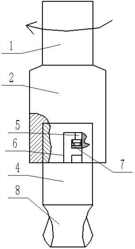
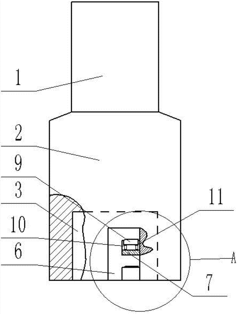
[0021] Such as figure 2 , 4 As shown in , 5, a detachable cutter for milling machine includes a first connecting portion and a second connecting portion, the first connecting portion includes a handle 1, the handle 1 is connected to the connecting sleeve 2, and the lower end surface of the connecting sleeve 2 is provided with Slot hole 3, the side wall of slot hole 3 is evenly provided with a plurality of vertical grooves 6 parallel to the axial centerline of connecting sleeve 2, according to the axial centerline symmetry of connecting sleeve 2, the two vertical grooves 6 are opposite A plurality of corresponding bumps 7 are arranged on the side surfaces, and grooves 10 are arranged on the surface of the bumps 7 facing the upper end surface of the connecting sleeve 2, and a jacking block 9 is arranged in the groove 10, and springs are passed on both sides of the lower end of the jacking block 9. 11 is connected with the bottom surface of groove 10.

[0022] Such as image 3 A


PUM


Abstract

The invention relates to the field of machining, in particular to a detachable cutter for a milling machine. The detachable cutter for the milling machine comprises a first connection portion and a second connection portion. The first connection portion comprises a cutter handle. The cutter handle is connected with a connection sleeve. A groove hole is formed in the lower end face of the connection sleeve. The side wall of the groove hole is evenly provided with multiple vertical grooves parallel to the axial center line of the connection sleeve. Opposite side faces of two symmetrical vertical grooves are each provided with multiple corresponding convex blocks. The face, facing the upper end face of the connection sleeve, of each convex block is provided with a groove. Abutting blocks are arranged in the grooves. The two sides of the lower end of each abutting block are connected with the bottom face of the corresponding groove through springs. The second connection portion comprises a connector matched with a groove hole of the connection sleeve. The outer edge of the connector is provided with multiple stop blocks which are symmetrical about the axial center line of the connector. The lower end face of the connector is provided with a milling cutter. The detachable cutter for the milling machine is simple in design structure and convenient to operate, improves the work efficiency, has the extending and retracting function and is suitable for machining of deep holes or grooves.

Description


Claims


Application Information

Patent Timeline
Owner 郑州佳泰机电科技有限公司
Why Eureka
Try Eureka