Method and device for receiving response in wireless communication network based on time division duplex
A technology of receiving response and wireless communication, which is applied in the field of receiving response to achieve the effect of shortening waiting time, reducing the number of retransmissions, and shortening waiting time
- Summary
- Abstract
- Description
- Claims
- Application Information
AI Technical Summary
Benefits of technology
Problems solved by technology
Method used
Image

Examples
Embodiment 1
[0099] Embodiment 1: The multiple reception responses that need to be sent are allocated to multiple consecutive uplink subframes substantially evenly.
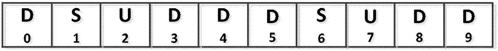
[0100] In this case, the number of reception acknowledgments that need to be sent in one uplink subframe decreases linearly. Figures 3a-3d It is a schematic diagram of downlink HARQ timing of uplink / downlink configurations 2, 3, 4 and 5 according to Embodiment 1 of the present invention.
[0101] see Figure 3a , where D 6 -D 11 are 6 consecutive downlink subframes, and U14 is the first uplink subframe after them. S d2 As a downlink special subframe, it also undertakes the task of downlink transmission, and the distance between U4 and U5 and Sd2 is too close to meet the processing time requirements of the receiver, so U14 becomes the first available after Sd2 (correspondingly, for Sd2, the minimum delay for receiving a response is the time interval between it and U14, that is, 12 subframes). So far, the user equipment n
Embodiment 2
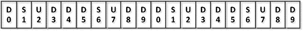
[0108] Example 2: In Figures 3a-3d In the shown embodiment 1, there may be some uplink subframes carrying more sending tasks of receiving acknowledgments, for example Figure 3d U4 and U5 shown on the right side respectively correspond to 8 downlink subframes. In order to further reduce the number of corresponding / associated downlink subframes required for a single subframe, according to Embodiment 2, it is proposed to use the special subframe S u Also used to send and receive acknowledgments. see Figure 4 , Figure 4 It is a schematic diagram of the further improved downlink HARQ timing of the uplink / downlink configuration 5 according to the specific embodiment 2 of the present invention.
[0109] Such as Figure 4 As shown, Sd2, D6-D19 have a total of 15 subframes, if according to Figure 3d For example, it is necessary to use U4 to provide the receiving response of Sd2, D6-D12 totaling 8 subframes, and use U5 to provide the receiving response of D13-D19 totaling 7
Embodiment 3
[0115] Embodiment 3: Dynamically define the HARQ timing scheme according to the number of received acknowledgments provided according to the actual needs of acknowledgment
[0116] Relatively speaking, the solutions of Embodiment 1 and Embodiment 2 are static, wherein, according to the static definition in advance, eNB and UE clearly predict how to perform the transmission of the reception response, that is, which The transmission of the subframe is acknowledged.
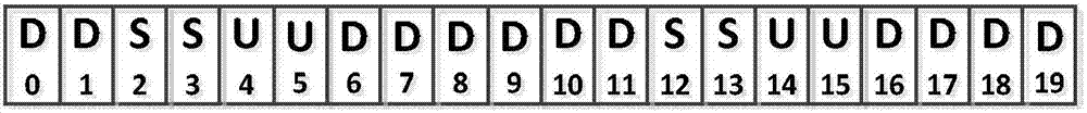
[0117] The scheme of embodiment 1-2 is undoubtedly feasible, of course, there may still be further improvements. see Figures 5a-5b , which is a schematic diagram of further improved downlink HARQ timing of uplink / downlink configuration 5 according to a specific embodiment of the present invention.
[0118] This is because, in some cases, some downlink subframes may not send downlink data. For these downlink subframes without data transmission, there is no need to provide reception acknowledgments. In other words
PUM
 Abstract
Description
Claims
Application Information
 - R&D Engineer
- R&D Manager
- IP Professional
- Industry Leading Data Capabilities
- Powerful AI technology
- Patent DNA Extraction
Browse by: Latest US Patents, China's latest patents, Technical Efficacy Thesaurus, Application Domain, Technology Topic.
© 2024 PatSnap. All rights reserved.Legal|Privacy policy|Modern Slavery Act Transparency Statement|Sitemap