Wastewater solid-liquid separator and separation method thereof

A technology of solid-liquid separation and separation method, which is applied in chemical instruments and methods, animal husbandry wastewater treatment, biological water/sewage treatment, etc., to achieve the effect of reducing the difficulty of sewage treatment

Inactive Publication Date: 2017-09-15
福建省蓝深环保技术股份有限公司
View PDF4 Cites 2 Cited by
  • Summary
  • Abstract
  • Description
  • Claims
  • Application Information

AI Technical Summary

Problems solved by technology

[0003] In view of the above technical problems, the present invention provides a water-floating solid-liquid se

Method used


Image

  • Wastewater solid-liquid separator and separation method thereof
  • Wastewater solid-liquid separator and separation method thereof

Examples


Embodiment Construction

[0028] The specific implementation manner of the present invention is described with reference to the drawings and examples.

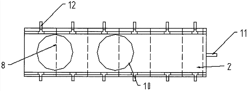
[0029] like figure 1 As shown, the solid-liquid separation equipment includes a solid-liquid separation cabinet 1, a mud-water separation tank 2 and an upflow anaerobic reaction tank 3;

[0030] The inside of the solid-liquid separation cabinet 1 is provided with a plurality of multi-layer filter components 5, and the multi-layer filter components 5 include a bottom plate and four side walls, and the four side walls are respectively three screens and a The discharge door, the bottom plate is a bottom plate screen; the top of the multi-layer filter component 5 is provided with a water inlet distribution pipe 4;

[0031] Below the multi-layer filter part 5 is the water collection area 6; the water collection area 6 is connected to the anaerobic water distribution pipe 9 through the water collection pipe 7, and the anaerobic water distribution pipe 9 is ins


PUM


Abstract

The invention relates to a wastewater solid-liquid separator and a separation method thereof, which belongs to the technical field of sewage treatment. A plurality of multi-layered filter elements are arranged in a solid-liquid separation cabinet, the four sidewalls of each multi-layered filter element are three screens and a discharge door, and the bottom plate is a bottom plate screen; an influent water distribution pipe is arranged on the top of each multi-layered filter element; a water collection area is under each multi-layered filter element; the water collection areas are connected to anaerobic water distribution pipes through a water collection pipe, and the anaerobic water distribution pipes are mounted in upflow anaerobic reaction tanks; the tops of the upflow anaerobic reaction tanks are connected to a sludge-water separation tank; sludge funnels are arranged at the joints between the bottom of the sludge-water separation tank and the upflow anaerobic reaction tanks; the sludge-water separation tank is also provided with sludge outlet pipes, and the sludge outlet pipes are connected to a sludge suction pump; and the top of the sludge-water separation tank is also provided with a water outlet. The invention comprehensively solves sludge and colloidal substances in the pretreatment of piggery wastewater, water which finally comes out of a water outlet pipe does not carry sludge, little colloid or even no colloid exits in the water, and thereby the difficulty of subsequent sewage treatment is decreased.

Description


Claims


Application Information

Patent Timeline
Owner 福建省蓝深环保技术股份有限公司
Why Eureka
Try Eureka