Method of controlling hydraulic valve to be reversed through electric control system
An electronic control system and hydraulic valve technology, applied in the field of reversing valve reversing, can solve the problem of reducing the fluid flow rate, the valve port on the valve core and the valve port on the valve body are not accurately aligned, and the pressure of the valve body inlet port is high, etc. problems, to avoid extreme stress
- Summary
- Abstract
- Description
- Claims
- Application Information
AI Technical Summary
Problems solved by technology
Method used
Image

Examples
Example Embodiment
[0030] Example 1
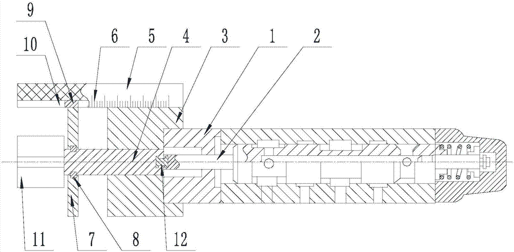
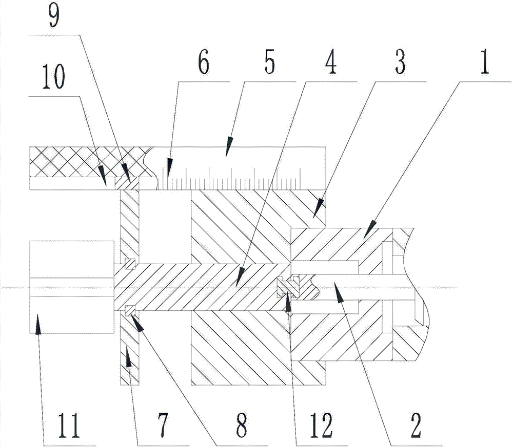
[0031] Such as Figure 1-Figure 3 As shown, a method for controlling the reversal of a hydraulic valve through an electronic control system of the present invention includes the following steps:
[0032] Step A Installation: Install the mounting block 3 on the end of the valve body 1 that is penetrated by the valve core 2, and install the screw 4 on the end of the valve core 2 that penetrates the valve body 1, and the screw 4 can perform relative to the valve core 2. Rotate independently, the end of the screw 4 away from the valve core 2 is matched with the threaded hole and located on the side of the threaded hole away from the valve body 1;
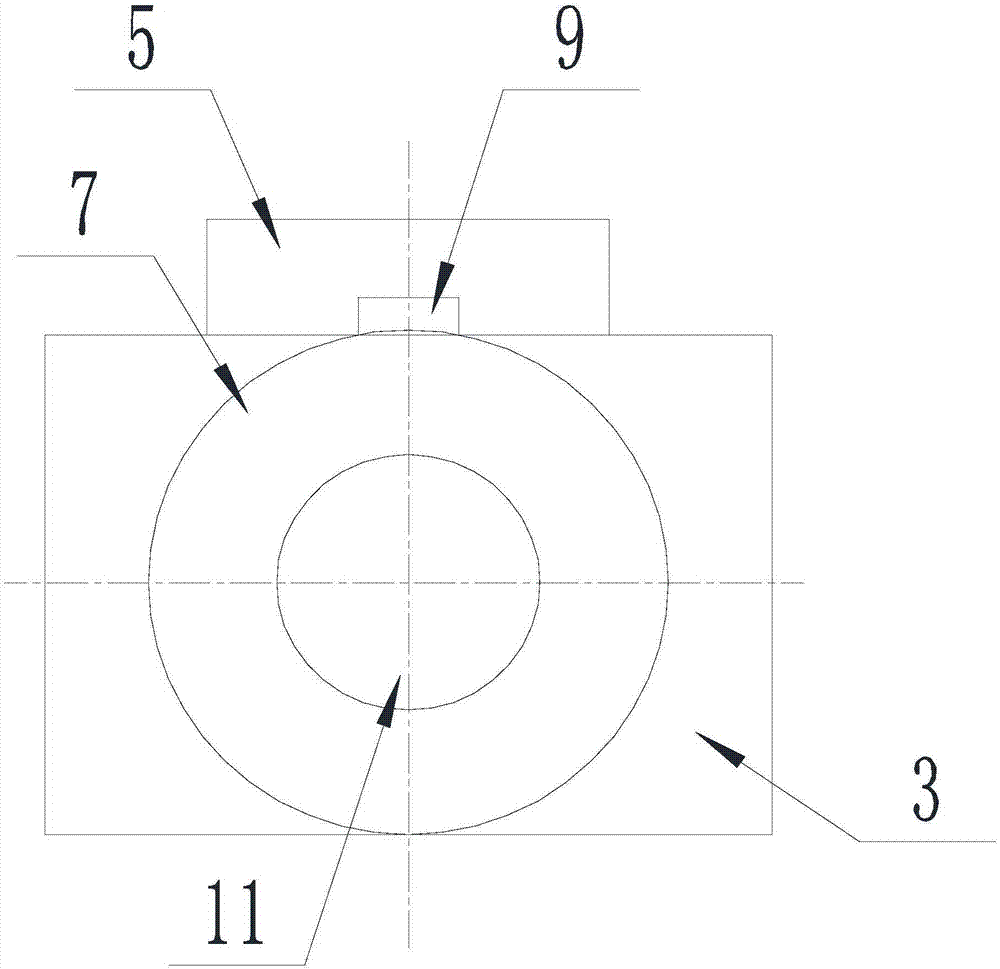
[0033] A comparison block 5 is installed on the side wall of the mounting block 3, and the end of the comparison block 5 far from the valve body 1 is suspended above the screw 4, and on the side wall of the comparison block 5 along the axis of the valve core 2 Set with scale line 6;
[0034] Step B Reversing: Trigger the input
Example Embodiment
[0037] Example 2
[0038] The present invention is based on Embodiment 1, and further illustrates the present invention.
[0039] Such as Figure 1-Figure 3 As shown, the present invention is a method for controlling the reversal of a hydraulic valve through an electronic control system, and the axis of the threaded hole coincides with the axis of the valve core 2.
[0040] Further, a connecting ring 7 is sleeved on the side of the screw 4 that is away from the valve core 2, and the outer wall of the connecting ring 7 is in contact with the end of the comparison block 5 close to the screw 4. The connecting ring 7 is in contact with the comparison block 5, which is convenient for the user to judge the moving distance of the screw 4 smoothly and accurately.
[0041] Further, the connecting ring 7 is clamped with the screw 4 through a spring stop ring 8. The connecting ring 7 can independently rotate relative to the screw 4, and a guide block 9 is provided on the outer wall of the connecti
Example Embodiment
[0042] Example 3
[0043] The present invention is based on Embodiment 1, and further illustrates the present invention.
[0044] Such as Figure 1-Figure 3 As shown, the present invention is a method for controlling the reversal of a hydraulic valve through an electronic control system. A connecting block 12 whose axis coincides with the axis of the valve core 2 is provided between the screw 4 and the valve core 2. The connecting block 12 The longitudinal section of is an I-shaped, one end is inserted into the screw 4, and the other end is inserted into the valve core 2. The screw 4 is rotatably connected with the valve core 2 through the connecting block 12.
PUM
 Abstract
Description
Claims
Application Information
 - R&D Engineer
- R&D Manager
- IP Professional
- Industry Leading Data Capabilities
- Powerful AI technology
- Patent DNA Extraction
Browse by: Latest US Patents, China's latest patents, Technical Efficacy Thesaurus, Application Domain, Technology Topic.
© 2024 PatSnap. All rights reserved.Legal|Privacy policy|Modern Slavery Act Transparency Statement|Sitemap