Piezoelectric windmill

A technology of electric windmills and piezoelectric vibrators, applied to electrical components, piezoelectric effect/electrostrictive or magnetostrictive motors, generators/motors, etc., can solve low reliability, poor wind speed adaptability, piezoelectric Problems such as two-way deformation of the vibrator achieve strong wind speed adaptability and high reliability

Active Publication Date: 2017-11-17
ZHEJIANG NORMAL UNIVERSITY
View PDF10 Cites 2 Cited by
  • Summary
  • Abstract
  • Description
  • Claims
  • Application Information

AI Technical Summary

Benefits of technology

The present technology allows for precise control over both resonance frequencies (natural) and winding speeds without compromising on its performance or durability. This means that it can be used with high-reliability devices such as sensors and actuators.

Problems solved by technology

This patented technical problem addressed in this patents relates to improving the performance and lifespan of miniature or thin film piezostimulatory (PZ) wires used with sensory networks in various applications like healthcare facilities. Current methods involve replacing worn out PZ wire segments frequently due to factors including environmental concerns associated with their usage environment. Additionally, current designs require limited limits on how much space they can be placed within them without affecting their functioning negatively impact its overall effectiveness over time.

Method used


Image

  • Piezoelectric windmill
  • Piezoelectric windmill

Examples


Embodiment Construction

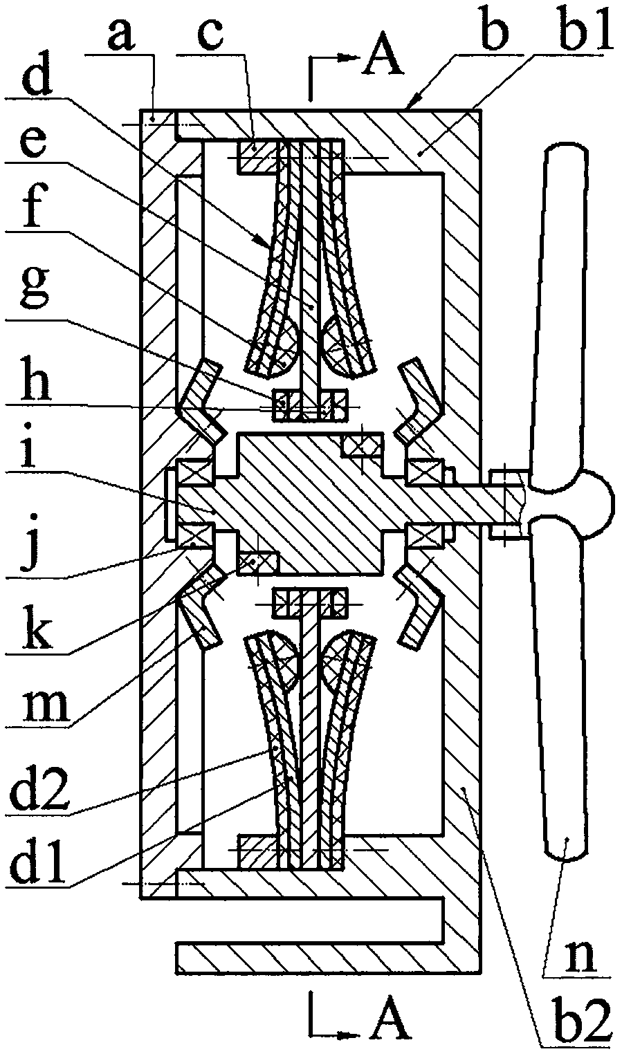
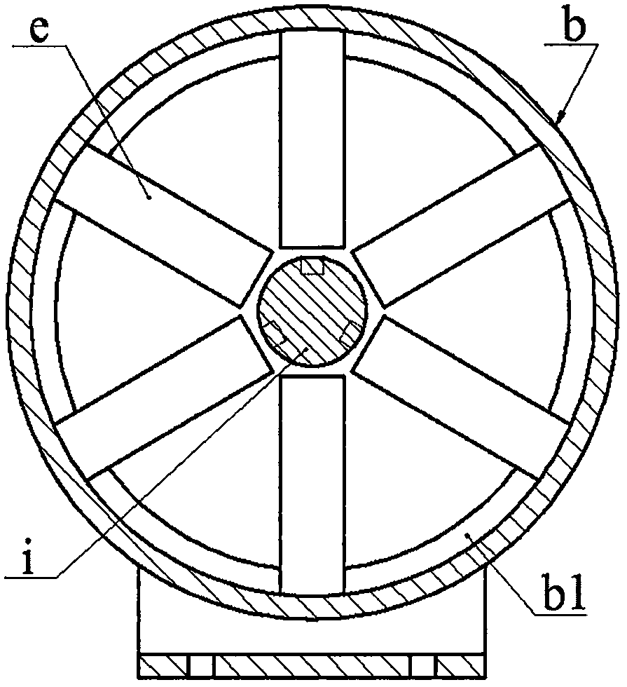
[0009] The end cover a is installed on the shell b through screws, and the buffer spring m is installed on the end cover a and the bottom wall b2 of the shell b through screws; The piezoelectric vibrator d and the excitation reed e are installed. The piezoelectric vibrator d is bonded by the substrate d1 and the piezoelectric sheet d2. The substrate d1 is installed close to the excitation reed e. The number of piezoelectric vibrators d on both sides of the excitation reed e Equal and symmetrical arrangement; the free end of the piezoelectric vibrator d is installed with a top block f via screws, and the top block f leans against the excitation reed e, and the free end of the excitation reed e is installed with a mass block h and an excited magnet through screws g; the left and right ends of the rotating shaft i are respectively installed on the end cover a and the bottom wall b2 of the housing b through the bearing j, and the two sections of the rotating shaft i are evenly install


PUM


Abstract

The present invention relates to a piezoelectric windwill and belongs to the field of piezoelectric power generation. An end cover is arranged on a shell. The end cover and the shell are provided with buffer reeds. Piezoelectric vibrators and excitation reeds are arranged on the annular boss of the shell. The substrates of the piezoelectric vibrators are arranged closer to the excitation reeds. The free ends of the piezoelectric vibrators are provided with top blocks. The top blocks abut against the excitation reeds. The free ends of the excitation reeds are provided with mass blocks and excited magnets. The two ends of a rotating shaft are respectively arranged on the end cover and the shell through a bearing. The two cross sections of the rotating shaft are uniformly provided with excitation magnets. The opposite magnetic poles of excitation magnets and excited magnets are oppositely arranged. The right end of the rotating shaft extends out of the bottom wall of the shell. A blade is arranged at the right end of the rotating shaft. Before the installation of the piezoelectric vibrators, the piezoelectric vibrators are of a flat and straight structure. After the installation of the piezoelectric vibrators, the piezoelectric vibrators are of a bent structure. During the non-working stage, the maximum compressive stress on a piezoelectric plate is 50% of the allowable value thereof. According to the invention, the system is wide in fundamental frequency adjustable range, and strong in wind speed adaptability. Meanwhile, the piezoelectric plate only bears the compressive stress, so that the reliability is high.

Description


Claims


Application Information

Patent Timeline
Owner ZHEJIANG NORMAL UNIVERSITY
Why Eureka
Try Eureka