transducer

a transducer and impedance matching technology, applied in the direction of transducer casings/cabinets/supports, electric transducers, electrical apparatus, etc., can solve the problems of speaker efficiency, about 1%, and difficulty in achieving proper impedance matching between acoustic and acoustic, so as to achieve efficient use of electrical power

Active Publication Date: 2017-02-09
GRABER CURTIS E
View PDF12 Cites 0 Cited by
  • Summary
  • Abstract
  • Description
  • Claims
  • Application Information

AI Technical Summary

Benefits of technology

The technical effect of this patented technology makes it possible for sensors to use their electricity more effectively without being affected by external factors like weather or other environmental conditions.

Problems solved by technology

This patented technical solution describes how small speakers have been developed but they still require significant amounts of electricity from their own battery because there is no effective method for adjusting them based on factors like resonant frequencies (R), inductive forces generated by moving parts called motors, and temperature differences caused by different materials involved.

Method used


Image

  • transducer
  • transducer
  • transducer

Examples


Embodiment Construction

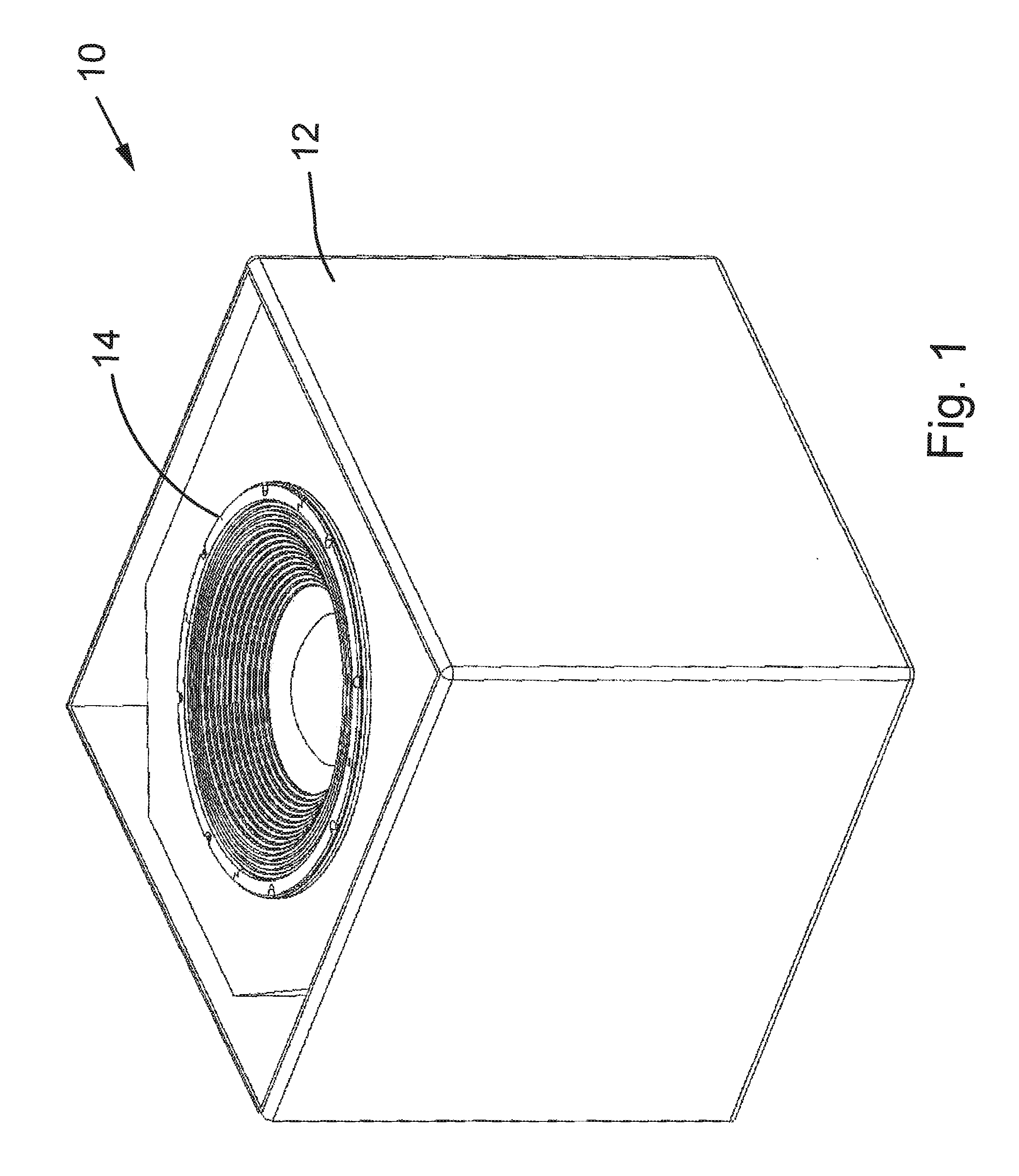
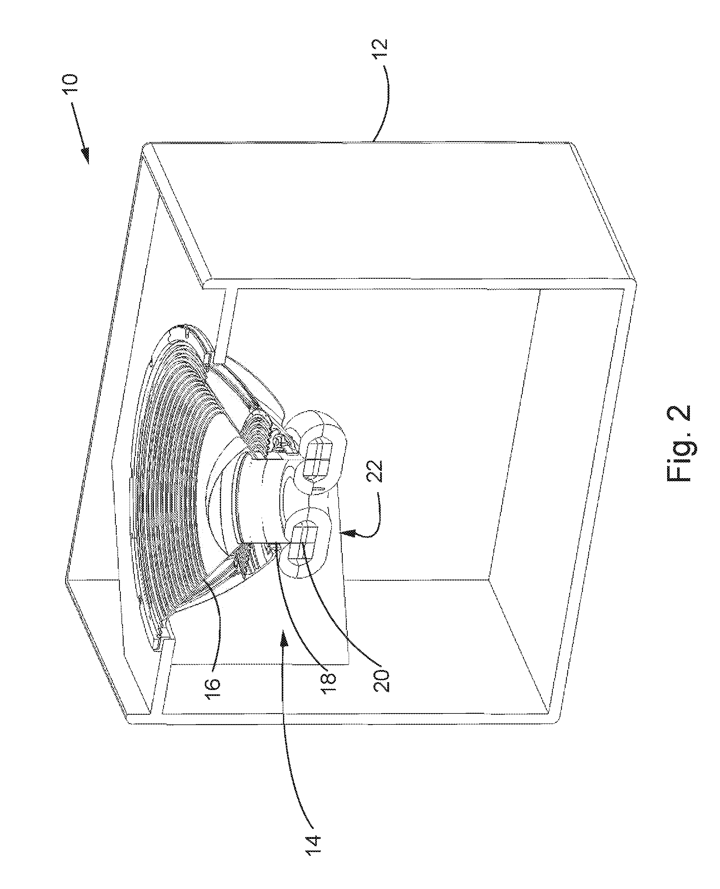
[0038]Referring now to the drawings, and more particularly to FIGS. 1 and 2, there is shown a speaker system 10 including an enclosure 12 and a transducer 14 in the form of an acoustic speaker 14. Speaker 14 includes a driven element 16-20 that is a speaker diaphragm 16 or cone 16, a collar 18 and a voice coil 20. Diaphragm 16 is suspended around its periphery and is moved by collar 18 to produce movements of air to thereby produce sound. Voice coil 20 is a winding of wire coupled to the collar 18 that is positioned in a magnetic field of a magnet assembly 22.

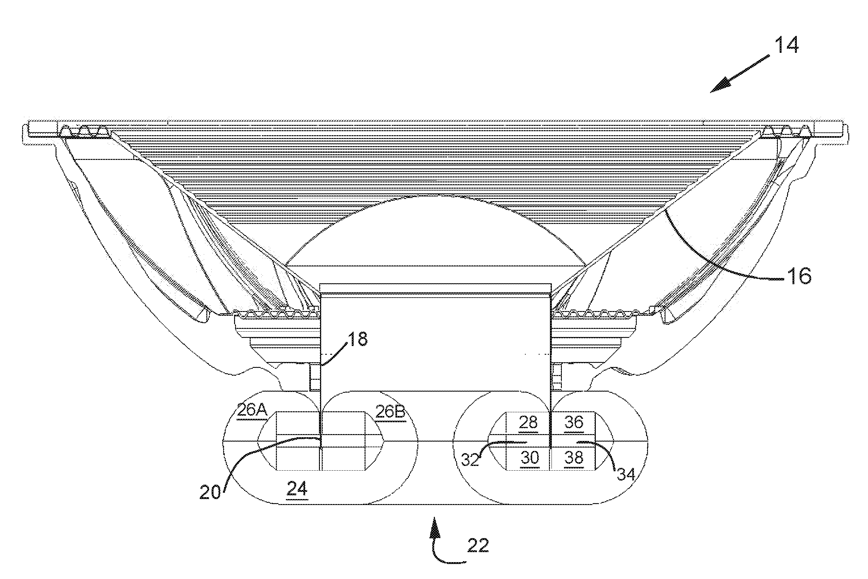
[0039]Now additionally referring to FIG. 3, there is shown a cut away view of speaker 14 showing more details of magnet assembly 22 which includes ferrous members 24, 26A, 26B magnets 28, 30, 36 and 38, and ferrous members 32 and 34. Ferrous members 24, 26A and 26B together have a combined shape that is similar to a nearly closed C-shape, with collar 18 passing therethrough. Ferrous members 24, 26A and 26B are arranged and shaped


PUM


Abstract

A transducer including a driven element and a magnet assembly. The magnet assembly is coupled to the driven element and includes a first and a second magnet, and a ferrous member. Each of the magnets have a first and second magnetic pole. The first magnetic pole of the first magnet and the first magnetic pole of the second magnet being proximate to each other and facing each other thereby defining a first magnetic zone therebetween, the first magnetic poles being similar, and the second magnetic poles being similar. The ferrous member couples a substantial amount of the magnetic field emanating from the second magnetic poles and directing the substantial amount of the magnetic field to a gap between the ferrous member and the first magnetic zone.

Description


Claims


Application Information

Patent Timeline
Owner GRABER CURTIS E
Why Eureka
Try Eureka