Device for comparing size of optical glass refractive index

A technology of comparative optics and refractive index, applied in the field of physical experiment demonstration equipment, can solve the problems of high cost of precision instruments, complex structure, immature technology, etc., and achieve the effect of short use process, simple structure and easy understanding

Inactive Publication Date: 2017-11-24
陕西镇安华兴特色农产品开发有限公司
View PDF5 Cites 1 Cited by
  • Summary
  • Abstract
  • Description
  • Claims
  • Application Information

AI Technical Summary

Benefits of technology

This new type of device uses an infrared light beam that can be easily compared with different types of plastic materials like acrylics without being too complicated. It also includes features such as line-of-light technology which makes it easier than traditional methods. Overall, this innovative design improves efficiency while making learning experience faster by providing accurate data on how well they are made from various materials.

Problems solved by technology

This patented technical problem addressed by this patents relates to improving the accuracy and efficiency of determining refractivity values (R) when making lens materials like fused quartz that require precise measurement techniques at an affordable price level.

Method used


Image

  • Device for comparing size of optical glass refractive index

Examples


Embodiment Construction

[0015] The present invention will be described in detail below in conjunction with the accompanying drawings and specific embodiments.

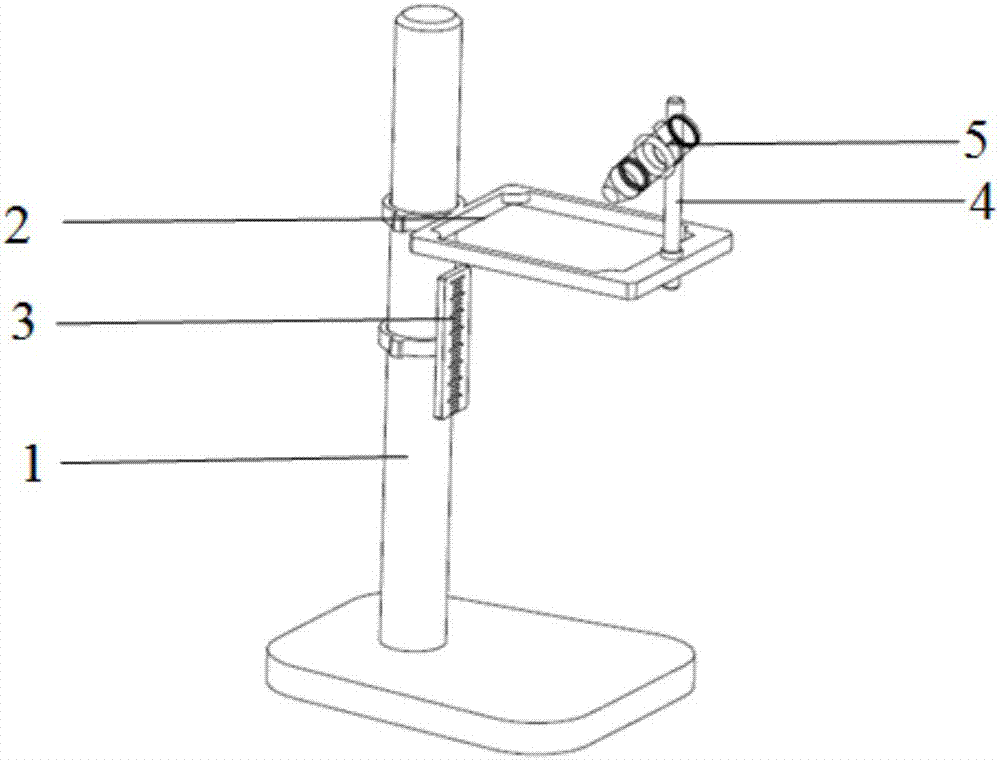
[0016] The invention is a device for comparing the refractive index of optical glass, comprising a fixed base 1, a glass clamping frame 2 is connected to the fixed base 1, a scale plate 3 is fixed directly below one end of the fixed base 1, and the scale plate 3 is close to the fixed base 1. The other end of the glass clamping frame 2 is connected with a clamping frame 4, and the laser pointer 5 is clamped in the clamping frame 4.

[0017] The light emitting wavelength of the laser pointer 5 is 650nm-670nm.

[0018] The size of the scale plate 3 is not less than 30cm×30cm.

[0019] The minimum scale value on the scale plate 3 is 1 mm.

[0020] The clamping frame 4 is a support for adjusting up and down.

[0021] When using a device for roughly comparing the refractive index of glass in the present invention, place the regular cuboid glass to


PUM

PropertyMeasurementUnit
Luminous wavelengthaaaaaaaaaa

Abstract

The present invention provides a device for comparing size of an optical glass refractive index. The device comprises a fixed pedestal which is connected with a clamping module, a scale plate is fixed at the lower portion of one side of the fixed pedestal, the scale plate is close to the fixed pedestal, the other end of the clamping module is connected with a clamping rack, and a laser pen is clamped in the clamping rack. The device employs linear propagation principle of the laser to visually compare the size of the optical glass refractive index, the principle is intelligible, the understanding is easy, and the device is suitable for teaching demonstration or simple optical glass distinguishing. The device is simple in structure, intelligible in principle and brief in usage process.

Description


Claims


Application Information

Patent Timeline
Owner 陕西镇安华兴特色农产品开发有限公司
Why Eureka
Try Eureka