Steel support pressurizing member and construction method thereof

A technology of steel support and components, which is applied in the direction of basic structure engineering, excavation, construction, etc., can solve the problems affecting the stability of the foundation pit and the vertical force of the support, so as to meet the requirements of technical quality control and save capital investment and force clear effect

Active Publication Date: 2017-12-08
CHINA MCC20 GRP CORP
View PDF5 Cites 0 Cited by
  • Summary
  • Abstract
  • Description
  • Claims
  • Application Information

AI Technical Summary

Benefits of technology

This technology allows for easy assembly or reassembly of component parts without causing damage during installation due to their properties such as strong materials' ability to resist bending loads over long periods of times. These composites also have clear stress zones on them which help it stay secure when installed properly under loadings. Overall this results in improved durability and efficiency compared to traditional methods like welding reinforcement bars alone.

Problems solved by technology

Technics problem addressed by this patented technical solution involves improving the design for an anchor used on concrete structures such as buildings or tunnels that use supports systems like those described earlier. These designs aim to solve issues related to these types of anchors' shortcomings - they can cause instability when under pressure due to their lengthy necks at one side compared to other parts of them (their centers). Additionally, there may be insufficient contact between the tip of each bolt and the base material if it pierces through its own hole instead of being properly supported.

Method used


Image

  • Steel support pressurizing member and construction method thereof
  • Steel support pressurizing member and construction method thereof

Examples


Embodiment Construction

[0013] Exemplary embodiments of the present disclosure will be described in more detail below with reference to the accompanying drawings. Although exemplary embodiments of the present disclosure are shown in the drawings, it should be understood that the present disclosure may be embodied in various forms and should not be limited by the embodiments set forth herein. Rather, these embodiments are provided for more thorough understanding of the present disclosure and to fully convey the scope of the present disclosure to those skilled in the art. It should be noted that, in the case of no conflict, the embodiments of the present invention and the features in the embodiments can be combined with each other. The present invention will be described in detail below with reference to the accompanying drawings and examples.

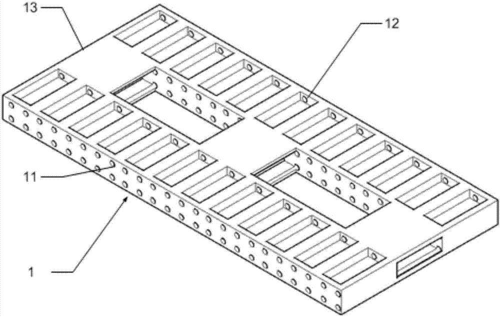
[0014] see figure 1 , the embodiment of the present invention provides a steel support compression member 1, which is characterized in that it includes: a first


PUM


Abstract

The invention provides a steel support pressurizing member. The steel support pressurizing member is characterized by comprising a first unit used for being connected with a first steel support, a second unit adopting the same structure as the first unit and used for being connected with a second steel support adjacent to the first steel support, and a connecting plate used for being connected with the upper ends and/or the lower ends of the first unit and the second unit, wherein a gap allowing a pressurizing part for exerting pressure onto the first unit and the second unit to be placed therein is formed between the first unit and the second unit. A standard member is manufactured by use of the characteristics of high material strength and reliable performance, section steel combined members can be assembled at any time according to deformation requirements of a foundation pit, supporting rod pieces are definitely stressed, a large contact area ensures that all the members are in uniform contact and are vertically stressed after the supporting rod pieces exert pre-stresses, and the technical quality control requirements are satisfied.

Description


Claims


Application Information

Patent Timeline
Owner CHINA MCC20 GRP CORP
Why Eureka
Try Eureka