Depressurization nipple for controlling annulus pressure of wellbore

A wellbore annulus and pressure technology, applied in the field of oil and gas drilling, can solve the problems of drilling fluid leakage, complicated drilling accidents, high cost, etc., and achieve the effect of reducing friction and improving energy conversion rate

Active Publication Date: 2018-01-12
CHINA UNIV OF PETROLEUM (BEIJING)
View PDF5 Cites 1 Cited by
  • Summary
  • Abstract
  • Description
  • Claims
  • Application Information

AI Technical Summary

Benefits of technology

This technology allows for better control over how much force or torque needs to be applied during drilling operations by reducing resistance when connecting to a drill string. It also includes features like absorbing excessive hydraulic impacts caused by fluctuations in pumping speed (the amount of fluid being lifted) while still allowing for efficient use of space within the borehole's casings. Additionally, this design helps improve efficiency through utilization of gravity forces acting upon the driller's equipment.

Problems solved by technology

This patented describes an improved way to manage the pressure inside the borehole when performing controlled pressure drills (CPWD). By controlling the amount of liquid injected or recovered with enough volume per unit area, the risk of damage due to excessive pressures becomes less than traditional methods like hydraulic fracturing techniques. Additionally, the proposed solution involves developing tools capable of maintaining stable annuli without losing too much weight on bit face.

Method used


Image

  • Depressurization nipple for controlling annulus pressure of wellbore
  • Depressurization nipple for controlling annulus pressure of wellbore
  • Depressurization nipple for controlling annulus pressure of wellbore

Examples


Embodiment Construction

[0021] The present invention will be described in detail below in conjunction with the accompanying drawings and embodiments.

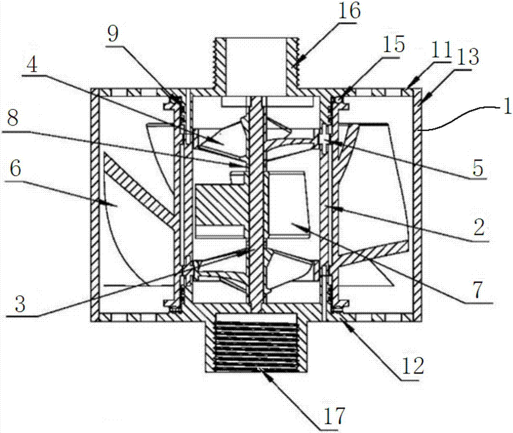
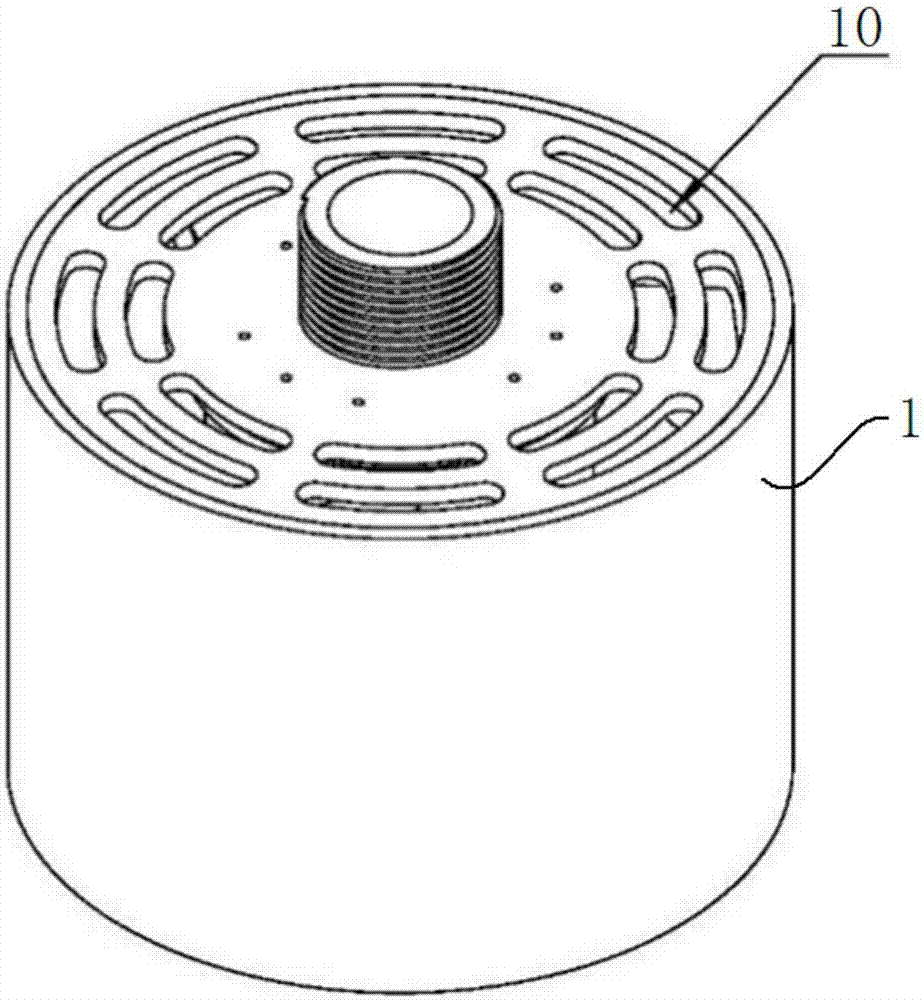
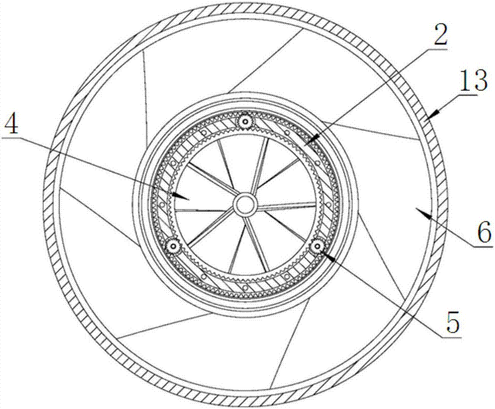
[0022] Such as Figure 1~3 As shown, the present invention proposes a pressure-reducing nipple 100 for controlling wellbore annular pressure, which includes a shell 1, and a cylindrical support wall 2 is fixed inside the shell 1, A fixed shaft 3 is provided, which is arranged on the axis of the support wall 2 . A power impeller 4 is respectively connected to the two ends of the fixed shaft 3. The outer edge of the power impeller 4 is an outer ring gear. A step-down impeller 6 is arranged for rotation, and the inner edge of the step-down impeller 6 is an inner ring gear, and the inner ring gear meshes with the transmission gear 5 .

[0023] Further, the casing 1 includes an upper cover 11 , a lower cover 12 and an outer side wall 13 , and the upper cover 11 and the lower cover 12 are welded to two ends of the outer side wall 13 respectively. The fixed


PUM


Abstract

The invention relates to a depressurization nipple for controlling the annulus pressure of a wellbore. The depressurization nipple is characterized by comprising a shell, wherein a barrel-shaped supporting wall is fixedly arranged inside the shell, a fixed shaft is fixedly arranged inside the shell, and the fixed shaft is disposed on the axis of the supporting wall; and the two ends of the fixed shaft are each rotationally connected with a power impeller, an outer tooth ring is arranged on the outer edge of each power impeller, the outer tooth rings are engaged with transmission gears rotationally connected to the supporting wall, a depressurization impeller is rotationally arranged outside the supporting wall, and an inner tooth ring is arranged on the inner edge of the depressurization impeller and engaged with the transmission gears.

Description


Claims


Application Information

Patent Timeline
Owner CHINA UNIV OF PETROLEUM (BEIJING)
Why Eureka
Try Eureka