Drive device matched with hanging rail

A technology of driving wheels and driven wheels, which is applied in the direction of transportation and packaging, elevators and lifts in buildings, etc. It can solve the problems of blocking seats, affecting the lighting of low-rise residents, and high installation and maintenance costs.

Pending Publication Date: 2018-01-26
NANJING UNIV OF SCI & TECH
View PDF7 Cites 0 Cited by
  • Summary
  • Abstract
  • Description
  • Claims
  • Application Information

AI Technical Summary

Benefits of technology

The technical effect that this new technology provides for improved control over vehicle movement by providing two wheels or guides along one rail line instead of just one. This allows vehicles to run more smoothly without getting stuck at certain points during turns due to changes in their orientation caused by factors like inclination angle or bouncing between tracks.

Problems solved by technology

This technical problem addressed by these inventions relating to improving the efficiency at construction sites when upgraded to new constructions while reducing expenses associated with erecting permanent lifts over older structures such as houses.

Method used


Image

  • Drive device matched with hanging rail
  • Drive device matched with hanging rail
  • Drive device matched with hanging rail

Examples


Embodiment Construction

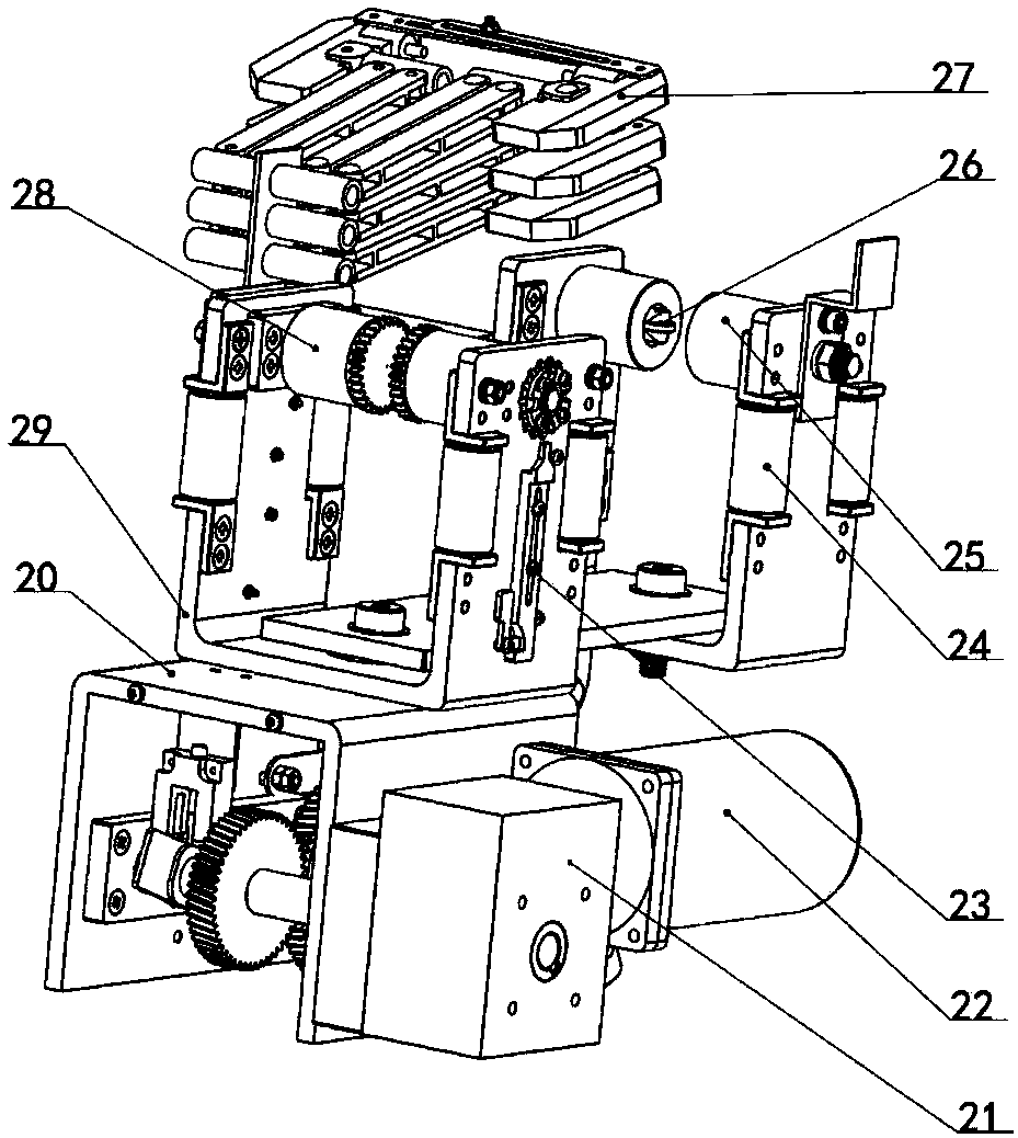
[0020] combine Figure 2 to Figure 7 , The driving device includes a U-shaped upper box body 29, a lower box body 20, a driving wheel 28, a speed reducer 21, a motor 22, and a transmission gear set. The upper box body 29 is fixedly connected with the lower box body 20 . The reducer 21 and the motor 22 are arranged on the lower casing 20, the reducer 21 is connected with the output shaft of the motor 22, and the driving wheels 28 have two and are symmetrically arranged on the two inner wall surfaces of the U-shaped upper casing 29 and are positioned on the guide rails. On the nylon pad 15 between the upper guide rail plate and the lower guide rail plate. The driving wheel 28 is axially arranged on a gear matched with the rack 14 . The output shaft of the speed reducer 21 is connected with the driving wheel 28 through the transmission gear set.

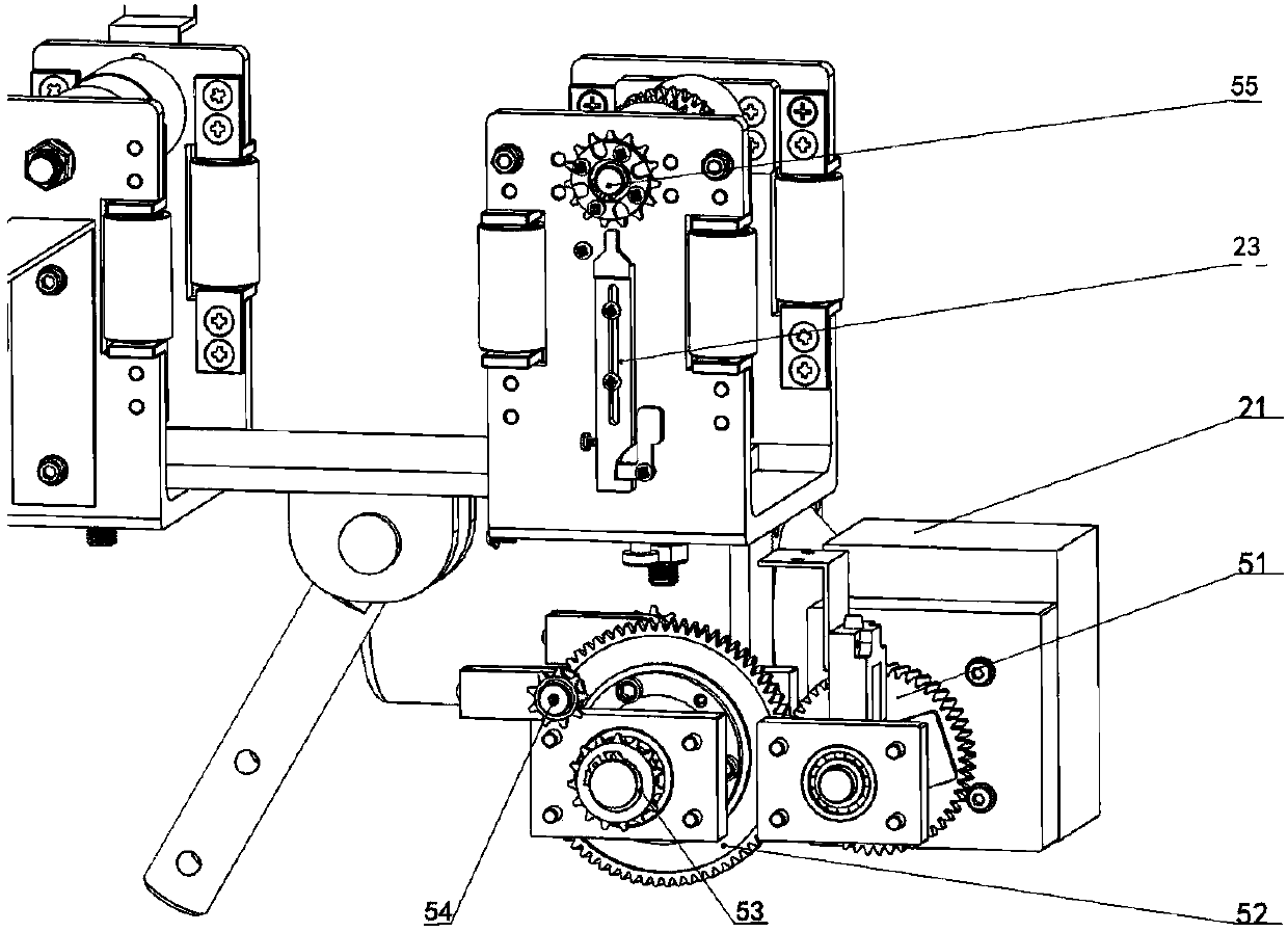
[0021] combine Figure 8 The transmission gear set includes a first helical gear 51 and a second helical gear 52 meshing with each ot


PUM


Abstract

The invention provides a drive device matched with a hanging rail. The drive device comprises a U-shaped upper box body, a second U-shaped upper box body, a lower box body, a drive wheel, a driven wheel, a guide wheel, a speed reducer, a motor and a transmission gear set. The upper box bodies are fixedly connected with the lower box body. The speed reducer and the motor are arranged on the lower box body, and the speed reducer is connected with an output shaft of the motor. The drive wheel is arranged on the surface of the inner wall of the U-shaped upper box body. An output shaft of the speedreducer is connected with the drive wheel through the transmission gear set. The second U-shaped upper box body is connected with the U-shaped upper box body. The driven wheel is arranged on the surface of the inner wall of the second U-shaped upper box body, and the driven wheel and the drive wheel are located on the same horizontal plane. The guide wheel is arranged on a driven wheel shaft of the driven wheel and rotates along an external track.

Description


Claims


Application Information

Patent Timeline
Owner NANJING UNIV OF SCI & TECH
Why Eureka
Try Eureka