Regulation and control system used for plant illumination

A control system and plant lighting technology, applied in lighting devices, botanical equipment and methods, applications, etc., can solve the problems of high energy consumption, general performance parameters, fixed light distribution ratio, etc., to promote plant photosynthesis and shorten growth. cycle, the effect of accelerating plant growth

Inactive Publication Date: 2018-01-26
WUXI HAOYU ENERGY SAVING ENVIRONMENTAL PROTECTION EQUIP CO LTD
View PDF4 Cites 0 Cited by
  • Summary
  • Abstract
  • Description
  • Claims
  • Application Information

AI Technical Summary

Benefits of technology

The present in this new technology uses two types of lights - one called yellow or green (RGB) and another called white or purple color – to stimulate vegetation faster during low temperatures compared to traditional methods like heaters. It achieves these benefits through adjustable ratio settings between them based upon environmental factors such as temperature.

Problems solved by technology

This patent describes various technical problem addressed in these inventions relating to improving greenhouse crops' ability to grow without interference from external environmental factors like temperature fluctuations during winter months when temperatures fall below certain levels. Existing methods involve manually adjusted fluorescent lamps that emit specific colors based solely upon their own characteristics, which results in unsatisfactory light qualities at varying times throughout each growing period. Additionally, existing techniques require expensive equipment and may result in reduced yield rates over time.

Method used


Image

  • Regulation and control system used for plant illumination

Examples


Embodiment Construction

[0018] Below in conjunction with accompanying drawing, technical scheme of the present invention is described in further detail:

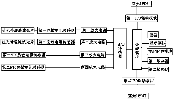
[0019] Such as figure 1 As shown, a control system for plant lighting includes a keyboard, a display module, a real-time clock module, a blue light band-pass filter, a first photoresistor sensor, a first amplification circuit, a red light band-pass filter, and a first Two photoresistor sensors, second amplifying circuit, first NTC thermistor sensor, third amplifying circuit, second NTC thermistor sensor, fourth amplifying circuit, A / D converter, processing module, first LED driving module , a second LED drive module, a red LED lamp, a blue LED lamp, a first radiator and a second radiator, the first NTC thermistor sensor is arranged on the substrate of the red LED lamp, and the second NTC thermistor sensor set on the substrate of the blue LED lamp; wherein,

[0020] The blue light bandpass filter, the first photoresistor sensor, the first amplifier


PUM


Abstract

The invention discloses a regulation and control system used for plant illumination. The system comprises a keyboard, a display module, a real-time clock module, a blue-light band-pass optical filter,a first photosensitive resistor sensor, a first amplification circuit, a red-light band-pass optical filter, a second photosensitive resistor sensor, a second amplification circuit, a first NTC thermosensitive resistor sensor, a third amplification circuit, a second NTC thermosensitive resistor sensor, a fourth amplification circuit, an A/D converter, a processing module, a first LED driving module, a second LED driving module, a red-light LED lamp and a blue-light LED lamp, the first NTC thermosensitive resistor sensor is arranged on a substrate of the red-light LED lamp, and the second NTCthermosensitive resistor sensor is arranged on a substrate of the blue-light LED lamp. According to the system, when light is insufficient, corresponding red and blue LED illumination light sources are turned on for supplementation so that illumination indexes can satisfy the requirement of plant growth, and the energy-saving effect is good.

Description


Claims


Application Information

Patent Timeline
Owner WUXI HAOYU ENERGY SAVING ENVIRONMENTAL PROTECTION EQUIP CO LTD
Why Eureka
Try Eureka