Automatic photoelectric sensor cleaning device
A photoelectric sensor and automatic cleaning technology, applied in the direction of cleaning methods, cleaning methods and utensils, chemical instruments and methods using gas flow, etc., can solve the problems of increasing the difficulty and labor intensity of manual cleaning, so as to save manpower and improve reliability Effect
- Summary
- Abstract
- Description
- Claims
- Application Information
AI Technical Summary
Benefits of technology
Problems solved by technology
Method used
Image

Examples
Embodiment 1
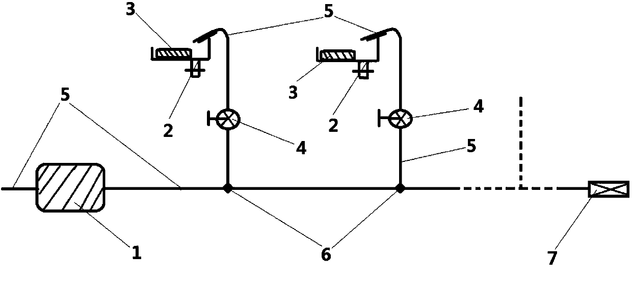
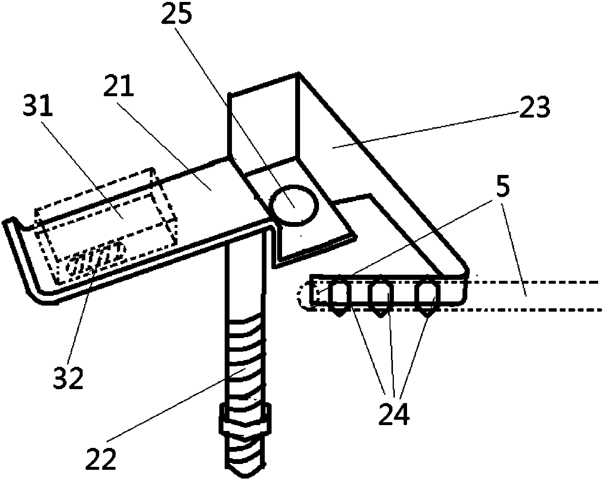
[0021] combine figure 1 and image 3 As shown, the present invention consists of an electromagnetic airflow valve 1, an end bracket 2, a flow valve 4, a gas pipe 5, a shunt pipe 6, and an air pressure detector 7.
[0022] The air inlet and the air outlet of the electromagnetic airflow valve 1 are respectively connected with air pipes 5, and the electromagnetic airflow valve 1 is connected with the computer control system of the production workshop. Electromagnetic air flow valve 1 controls the air flow of the entire pipeline system. In the computer control system, the electromagnetic airflow valve 1 is provided with a timing program. Every once in a while, preferably 15 minutes, the electromagnetic airflow valve 1 is opened, and the compressed air is introduced in the air pipe 5. The shunt pipe 6 is a three-way shunt air pipe, the left end is sleeved with the air pipe 5 , the middle end leads to an end support 2 , and the right end is sleeved with the air pipe 5 connected to th
Embodiment 2
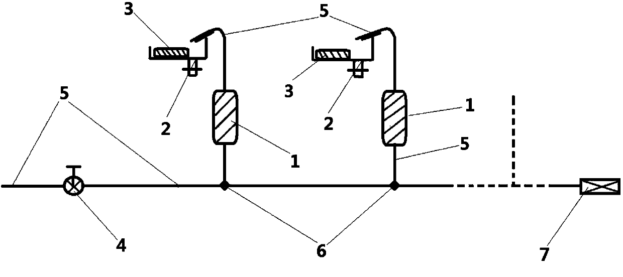
[0025] combine figure 2 and image 3 As shown, the present invention consists of an electromagnetic airflow valve 1, an end bracket 2, a flow valve 4, a gas pipe 5, a shunt pipe 6, and an air pressure detector 7.
[0026] Both ends of the flow valve 4 are respectively connected to the air pipe 5 , the left end leads to compressed air, and the right end leads to the first shunt pipe 6 . By adjusting the flow valve 4, the size of the airflow blowing to the photoelectric sensor probe 32 after the airflow is conducted can be controlled. The shunt pipe 6 is a three-way shunt air pipe, the left end is sleeved with the air pipe 5 , the middle end leads to an end bracket 2 , and the right end is sleeved with the air pipe 5 connected to the next shunt pipe 6 . An electromagnetic airflow valve 1 is provided between the end bracket 2 and the shunt pipe 6 . Electromagnetic airflow valve 1 is connected to the computer control system of the production workshop. The electromagnetic airflow
PUM
 Abstract
Description
Claims
Application Information
 - R&D Engineer
- R&D Manager
- IP Professional
- Industry Leading Data Capabilities
- Powerful AI technology
- Patent DNA Extraction
Browse by: Latest US Patents, China's latest patents, Technical Efficacy Thesaurus, Application Domain, Technology Topic.
© 2024 PatSnap. All rights reserved.Legal|Privacy policy|Modern Slavery Act Transparency Statement|Sitemap