Windproof device for portal crane
A technology for gantry cranes and windproof devices, which is applied to cranes, trolley cranes, traveling mechanisms, etc., can solve the problems of speeding up the walking speed, frequent use, and cranes falling off the track, etc., and achieves strong versatility, simple structure, and wide application range Effect
- Summary
- Abstract
- Description
- Claims
- Application Information
AI Technical Summary
Benefits of technology
Problems solved by technology
Method used
Image

Examples
Embodiment 1
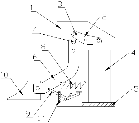
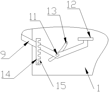
[0017] Such as figure 1 and figure 2 As shown, a gantry crane windproof device, which includes a fixed frame 1, the upper part of the fixed frame 1 is hinged with a pressure plate 2, the upper part of the pressure plate 2 is connected with a final shaft 3, and the lower part of the pressure plate 2 is hinged with an electric thrust device 4, the lower end of the electric thruster 4 is connected with a support plate 5, the support plate 5 is connected with the fixed frame 1, and the middle part of the fixed frame 1 is hinged with a push arm 6 matched with the pressure plate 2, and the described The upper end of the push arm 6 is provided with a pressure groove 7 matched with the pressure shaft 3, and the push arm 6 is sequentially hinged with a spring 8, a push rod 9 and a wedge 10 from top to bottom. connection, the middle part of the push rod 9 is provided with a guide shaft 11, the other end of the push rod 9 is connected with a pedal 12, and the lower part of the fixed frame
Embodiment 2
[0020] Such as figure 1 and figure 2 As shown, a gantry crane windproof device, which includes a fixed frame 1, the upper part of the fixed frame 1 is hinged with a pressure plate 2, the upper part of the pressure plate 2 is connected with a final shaft 3, and the lower part of the pressure plate 2 is hinged with an electric thrust device 4, the lower end of the electric thruster 4 is connected with a support plate 5, the support plate 5 is connected with the fixed frame 1, and the middle part of the fixed frame 1 is hinged with a push arm 6 matched with the pressure plate 2, and the described The upper end of the push arm 6 is provided with a pressure groove 7 matched with the pressure shaft 3, and the push arm 6 is sequentially hinged with a spring 8, a push rod 9 and a wedge 10 from top to bottom. connection, the middle part of the push rod 9 is provided with a guide shaft 11, the other end of the push rod 9 is connected with a pedal 12, and the lower part of the fixed frame
PUM
 Abstract
Description
Claims
Application Information
 - R&D Engineer
- R&D Manager
- IP Professional
- Industry Leading Data Capabilities
- Powerful AI technology
- Patent DNA Extraction
Browse by: Latest US Patents, China's latest patents, Technical Efficacy Thesaurus, Application Domain, Technology Topic.
© 2024 PatSnap. All rights reserved.Legal|Privacy policy|Modern Slavery Act Transparency Statement|Sitemap