On-resistance testing device

A technology of on-resistance and testing equipment, which is applied in the direction of measuring equipment, measuring resistance/reactance/impedance, measuring electrical variables, etc., and can solve the problems of low efficiency of on-resistance testers

Active Publication Date: 2018-03-30
GUANGDONG EVERWIN PRECISION TECH
View PDF3 Cites 2 Cited by
  • Summary
  • Abstract
  • Description
  • Claims
  • Application Information

AI Technical Summary

Problems solved by technology

[0003] Based on this, it is necessary to provide an on-resistance testing device with high

Method used


Image

  • On-resistance testing device
  • On-resistance testing device

Examples


Embodiment Construction

[0017] In order to facilitate the understanding of the present invention, the present invention will be described more fully below with reference to the associated drawings. Preferred embodiments of the invention are shown in the accompanying drawings. However, the present invention can be embodied in many different forms and is not limited to the embodiments described herein. On the contrary, these embodiments are provided to make the understanding of the disclosure of the present invention more thorough and comprehensive.

[0018] It should be noted that when an element is referred to as being “fixed” to another element, it can be directly on the other element or there can also be an intervening element. When an element is referred to as being "connected to" another element, it can be directly connected to the other element or intervening elements may also be present.

[0019] Unless otherwise defined, all technical and scientific terms used herein have the same meaning as co


PUM


Abstract

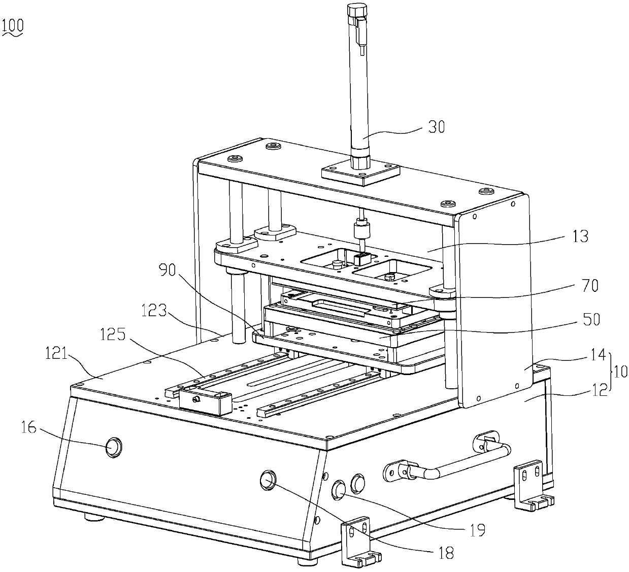
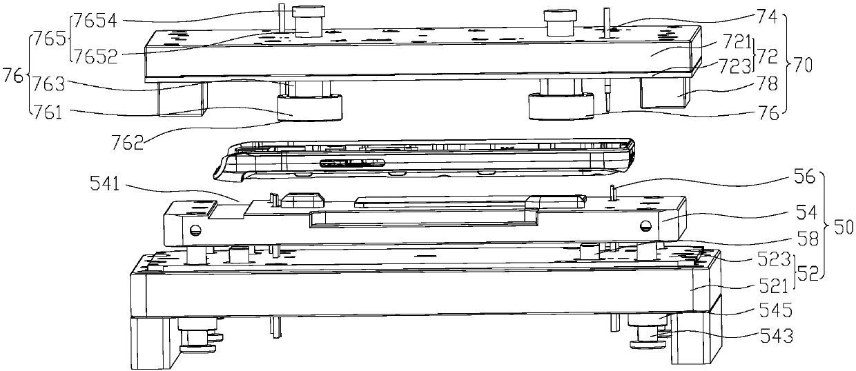
The invention relates to an on-resistance testing device, including a rack, a driving part, a lower test module and an upper test module. The lower test module includes a lower mounting plate group, afloating plate and a lower probe, the lower mounting plate group is arranged on the rack, the floating plate can be arranged on the lower mounting plate group in a liftable manner and a station carrying a workpiece is formed on the floating plate, and the lower probe is fixed on the lower mounting plate group and penetrates through the floating plate in a telescopic manner; the upper test moduleincludes an upper mounting plate group opposite to the lower mounting plate group, an upper probe and a prepressing component, the upper probe and the prepressing component convexly extends out of theupper mounting plate group and faces the surface of the lower mounting plate group, the driving part is connected with the upper mounting plate group, the upper mounting plate group is driven to be close to the lower mounting plate group to fall to enable the upper probe to abut against one side of the workpiece, when the upper mounting plate group falls, the prepressing component presses the floating plate relative to the lower mounting plate to enable the lower probe to extend out of the floating plate to abut against the other side of the workpiece in the station, and on-resistance testingis performed on the upper and lower sides of the workpiece at a time, thereby improving testing efficiency.

Description


Claims


Application Information

Patent Timeline
Owner GUANGDONG EVERWIN PRECISION TECH
Why Eureka
Try Eureka