Distributed image reconstruction method of radio interference array

An image reconstruction and distributed technology, applied in image data processing, 2D image generation, instruments, etc., can solve the problems of low operation efficiency and poor scalability.

Active Publication Date: 2018-04-06
SHANGHAI ASTRONOMICAL OBSERVATORY CHINESE ACAD OF SCI
View PDF3 Cites 2 Cited by
  • Summary
  • Abstract
  • Description
  • Claims
  • Application Information

AI Technical Summary

Problems solved by technology

[0004] What the present invention aims to solve is that the existing radio interference array image reconstruction method has the problems of low operating efficiency, poor scalability, and dependence on complex parameter set

Method used


Image

  • Distributed image reconstruction method of radio interference array
  • Distributed image reconstruction method of radio interference array
  • Distributed image reconstruction method of radio interference array

Examples


Embodiment Construction

[0045] In order to make the object, technical solution and advantages of the present invention clearer, the present invention will be further described in detail below in combination with specific examples and with reference to the accompanying drawings.

[0046] The original data used in this example is the data obtained by Karl G. Jansky VLA observation of supernova remnant 3C391 and then calibrated by the general astronomical application software CASA. The data format is Measurement Set, and the file name is 3c391_ctm_mosaic_spw0.ms.

[0047] First, view the data in the file 3c391_ctm_mosaic_spw0.ms, select the field of view of the target radio source, that is, the field ID number is 0; use CASA software to separate the observation data related to the field of view of the target radio source from the file 3c391_ctm_mosaic_spw0.ms and create a sub File 3c391_field0.ms.

[0048] Then, read the sub-file 3c391_field0.ms to obtain the observation frequency channel, uvw data, the re


PUM


Abstract

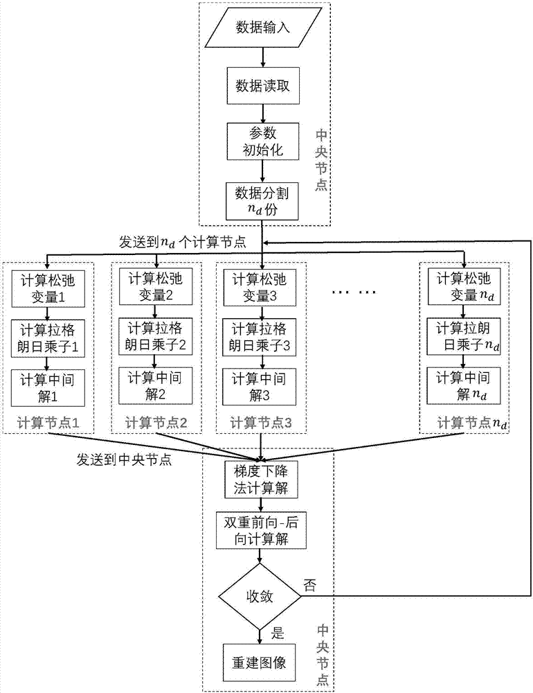
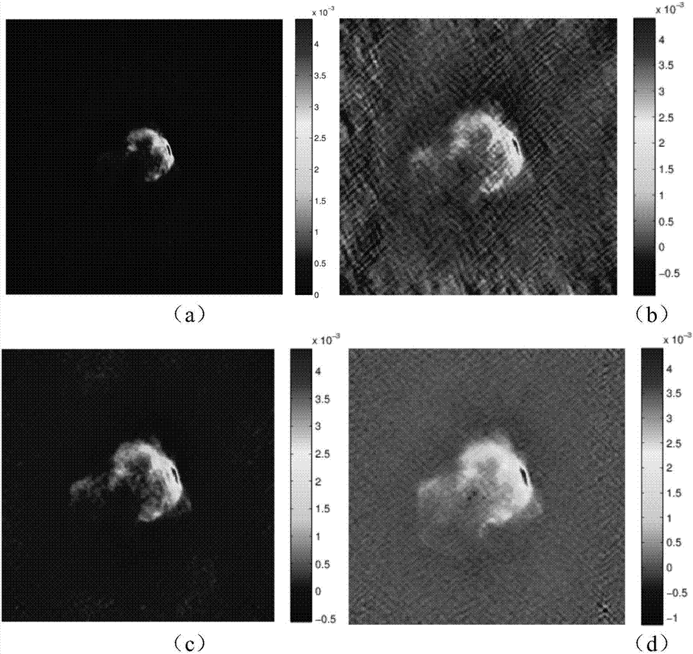
The invention discloses a distributed image reconstruction method of a radio interference array. An inverse problem of image reconstruction of the radio interference array is converted into a convex optimization problem under the equality constraint condition, an approximate ADMM (alternating direction method of multipliers) is used to solve the problem, and the quality of a finally reconstructedimage is higher than that via a present algorithm; data is segmented into multiple parts accurately and rapidly; and multiple calculation nodes are used for calculation, the parallel performance is higher, and the extensibility is high. The method can be used to obtain the reconstruction image directly needless of data post-processing steps, the dynamic range of the finally obtained image is wider, a celestial body of the extension structure is displayed more clearly, and the efficiency is higher compared with traditional methods.

Description


Claims


Application Information

Patent Timeline
Owner SHANGHAI ASTRONOMICAL OBSERVATORY CHINESE ACAD OF SCI
Why Eureka
Try Eureka