Livestock-breeding cub feeding device

A technology of a cub and an expansion device, which is applied in the field of animal husbandry, can solve the problems of death, waste, poor use effect, etc., and achieve the effects of improving feeding effect, simple structure and easy promotion.

Active Publication Date: 2018-05-01
盛瑜 +2
View PDF9 Cites 1 Cited by
  • Summary
  • Abstract
  • Description
  • Claims
  • Application Information

AI Technical Summary

Benefits of technology

This invention relates to an improved way for piglets that are fed by their own gut without blocking up any other things they shouldn't get inside them when eaten or drink from it. These improvements include simpler structures, lower prices, easier accessibility, effective nutritional supplementation, better digestion capabilities, and more efficient ways of delivering food into its gastrointestinal tract (GI).

Problems solved by technology

This technical problem addressed by this patented technology relates to improving the quality and quantity of crops that can be used for producing high value products like protein (such as fish meal) without compromising on their physiological properties. Current methods involve manually inserting an injector into each cowl neck where they feel something hard due to pressure applied when pushing it inside. These techniques may result in damage to tissue near these organs leading to decreased production rates over time. Additionally, current feeder devices only allow for limited movement within certain areas around the circumference of the animals being kept at home.

Method used


Image

  • Livestock-breeding cub feeding device
  • Livestock-breeding cub feeding device

Examples


Embodiment Construction

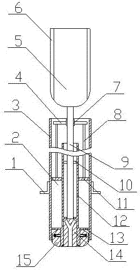
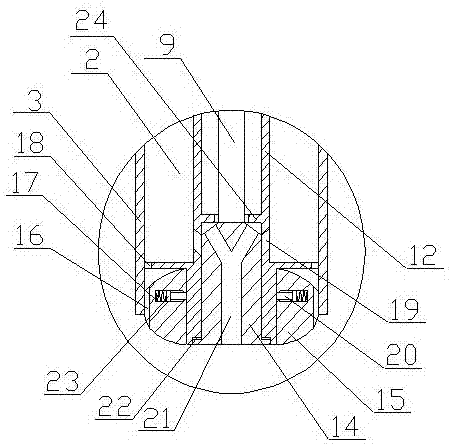
[0023] A feeding device for livestock breeding cubs of the present invention is realized in this way. When in use, when feeding livestock cubs, first put the food to be fed into the food cavity (2), and then hold the handle (5), Put one end of the main tube (3) into the cub's mouth, and keep the ring baffle outside the cub's mouth to prevent the main tube (3) from being directly inserted into the cub's mouth, and then push the handle into the cub's mouth (5), the grip rod (5) drives the push rod (9) to move, and the push rod (9) drives all parts except the main cylinder (3) and the annular baffle to move into the mouth of the cub, and the support block (15) Gradually protrude from the main body cylinder (3), the springs in the two annular grooves on the support block (15) are stretched, driving the support block (15) to expand, and then the support block (15) is supported on the cub's throat, and the cub Stretch the cub's throat, and then continue to push the handle (5). At this


PUM


Abstract

The invention discloses a livestock-breeding cub feeding device, and discloses a device capable of extending into a cub mouth, opening the cub throat, and then feeding food. Food can smoothly enter the cub stomach, and the feeding effect is improved. The livestock-breeding cub feeding device is characterized in that a thread is formed in the outer wall of a body cylinder, the body cylinder is sleeved with a limiting baffle, the limiting baffle is of an annular structure, and a thread is formed in the inner side of the limiting baffle, and is engaged with the thread in the outer wall of the body cylinder; a boosting cylinder is arranged in the body cylinder, an annular groove is formed in the inner wall of one end of the boosting cylinder, and a magnet sheet is arranged in the annular groove and connected with the boosting cylinder; a limiting ring is arranged on the inner wall of the boosting cylinder; two discharging openings are formed in the boosting cylinder and located at the lower portion of the limiting ring respectively, inlets of the discharging openings are small, and outlets of the discharging openings are large; a guiding plate is arranged on the inner wall of the boosting cylinder and located at the upper portion of the limiting ring, and is of an annular platy structure; a partition plate is arranged on the outer wall of the boosting cylinder.

Description


Claims


Application Information

Patent Timeline
Owner 盛瑜
Why Eureka
Try Eureka