Blind hole machining technology

A processing technology, blind hole technology, applied in the field of mechanical processing, can solve problems such as inconvenience in work

Inactive Publication Date: 2018-05-18
宁波高新区神台德机械设备有限公司
View PDF0 Cites 1 Cited by
  • Summary
  • Abstract
  • Description
  • Claims
  • Application Information

AI Technical Summary

Benefits of technology

This technology allows for automatic removal of chips from small openings without requiring manual labor. By attaching an electric magnet near one end of the cutting tool's bit-holder, it can keep the cutter clean during use. Afterward, when the drilling process starts with another step called backspinning, there are tiny particles on top of each other create pressure waves which help remove any dust stuck between them. These technical improvements make this method more efficient than previous methods like vacuum cleaner tools.

Problems solved by technology

The technical problem addressed in this patented text relates to how to efficiently clean up deadly pits from machinery components while maintaining their effectiveness during operation. Current methods require drilling multiple holes into each component before removal, which may cause further issues like damaging delicate surfaces on those components due to excessive burrs left behind when they were worked upon.

Method used


Image

  • Blind hole machining technology
  • Blind hole machining technology
  • Blind hole machining technology

Examples


Embodiment 1

[0026] Blind hole processing technology, including the following steps:

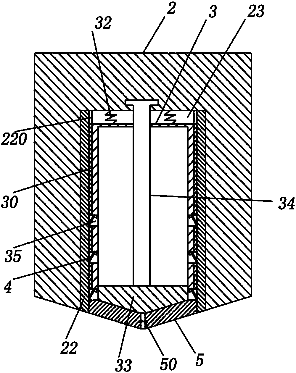
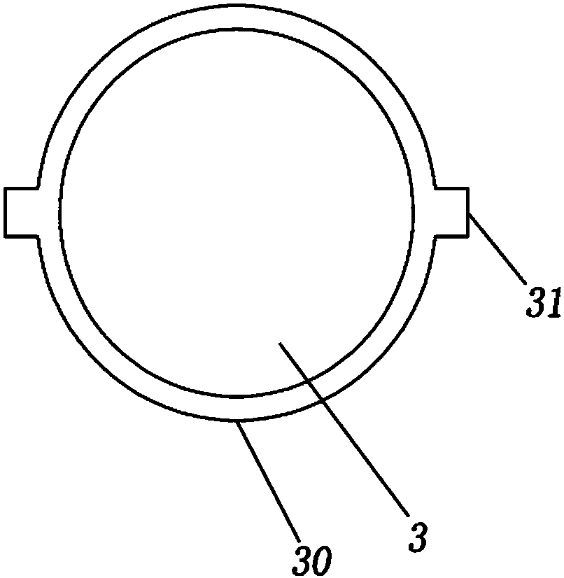
[0027] Step 1, preparation: prepare a drill 2 and a frame 1 with an electromagnet 10, the drill 2 is slidably connected with a chip suction pipe 3 that can automatically absorb wood chips by using the electromagnet 10. The specific structure is as follows:

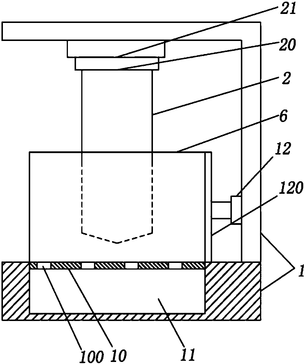
[0028] Such as figure 1 As shown, a rotating part that drives the drill 2 to rotate and a lifting part that drives the drill 2 to lift are installed on the top of the drill 2. The rotating part can directly select the motor 20 in the prior art, and the lifting part can directly select the hydraulic cylinder 21.

[0029] The frame 1 is welded with an electromagnet 10 for supporting the workpiece. The electromagnet 10 is in the shape of a net, and is provided with a number of chip leakage holes 100. The frame 1 is provided with a chip storage tank 11 located below the electromagnet 10. The chip hole 100 realizes collecting the wood chips on the electro

Embodiment 2

[0038] The difference between this embodiment and embodiment 1 is:

[0039] The length of the chip suction pipe 3 in step 1 is 33cm; the static electricity generated by the friction between the cotton layer 22 and the plastic layer 30 is 800uA;

[0040] In step 2, the rotating speed of the drill 2 is 1300r / min, and the falling speed of the drill 2 is 20mm / min; the depth of the blind hole is 12cm;

[0041] The operating current of the electromagnet 10 in step 3 is 1300A;

[0042] In step 4, the distance that the chip suction pipe 3 moves up automatically is 18cm.


PUM

PropertyMeasurementUnit
Lengthaaaaaaaaaa
Depthaaaaaaaaaa

Abstract

The invention belongs to the technical field of machining and particularly relates to a blind hole machining technology. The blind hole machining technology comprises the following steps that 1, preparation is conducted, specifically, a drilling tool and a rack with an electromagnet are prepared, and a chip attracting pipe capable of automatically attracting wood chips through the electromagnet isslidably connected into the drilling tool; 2, drilling is conducted, specifically, a workpiece is fixed to the electromagnet, the drilling tool and the chip attracting pipe continuously downwards move to form a blind hole while the drilling tool and the chip attracting pipe rotate, the rotating speed of the drilling tool is 1150-1300 r/min, and the falling speed of the drilling tool is 15-20 mm/min; 3, chip attracting is conducted, specifically, the electromagnet is started, the chip attracting pipe is fixed, meanwhile, in the upward moving process of the drilling tool, the wood chips in theblind hole are automatically attracted through the chip attracting pipe, and the working current of the electromagnet is 1000-1300 A; 4, discharging is conducted, specifically, the electromagnet is stopped, the chip attracting pipe automatically upwards moves, and after the chip attracting pipe moves out of the blind hole, the workpiece is taken down; and 5, chip discharging is conducted, specifically, in the process of continuous upward moving of the chip attracting pipe, the wood chips in the chip attracting pipe are automatically discharged. According to the scheme, the wood chips in the blind hole can be conveniently cleared away.

Description


Claims


Application Information

Patent Timeline
Owner 宁波高新区神台德机械设备有限公司
Why Eureka
Try Eureka