Orthopedic leg recovery auxiliary device
An auxiliary device and leg technology, which can be used in passive exercise equipment, physical therapy, etc., and can solve problems such as aggravating leg conditions and leg injuries.
- Summary
- Abstract
- Description
- Claims
- Application Information
AI Technical Summary
Benefits of technology
Problems solved by technology
Method used
Image

Examples
Embodiment 1
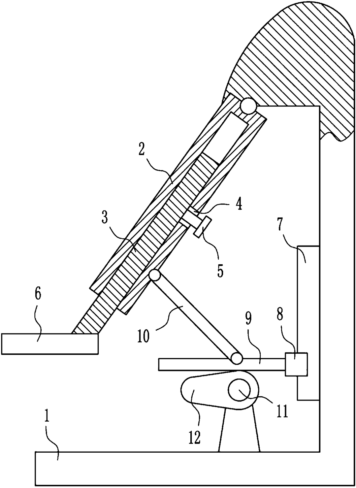
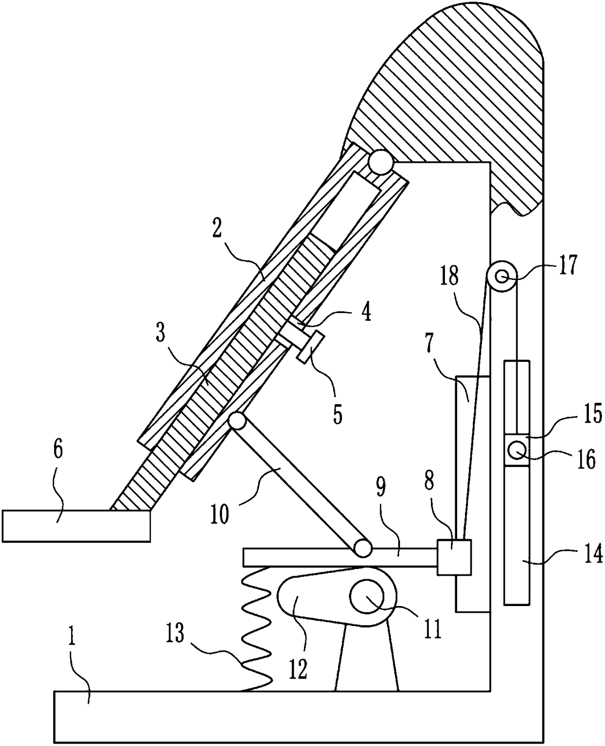
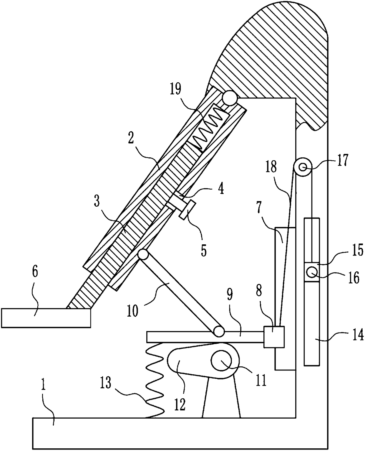
[0021] An orthopedic leg recovery aid, such as Figure 1-3 As shown, it includes a support frame 1, a sleeve 2, a movable rod 3, a bolt 5, a pedal 6, a slide rail 7, a first slider 8, a horizontal plate 9, a connecting rod 10, a motor 11 and a cam 12, and the support frame 1 A sleeve 2 is installed on the left side of the inner top, and a movable rod 3 is arranged in the sleeve 2. A pedal 6 is installed at the bottom of the movable rod 3. A threaded hole 4 is provided in the middle part of the right side of the sleeve 2, and a screw hole 4 is provided in the threaded hole 4. Bolt 5 is arranged, and bolt 5 is in contact with movable bar 3, and slide rail 7 is vertically installed on the lower part of the inner right side of support frame 1, and slide rail 7 is provided with the first slide block 8 that cooperates with it, and the first slide block 8 and slide The rail 7 is slidably matched, and the middle part of the left side of the first slider 8 is installed with a horizontal p
Embodiment 2
[0023] An orthopedic leg recovery aid, such as Figure 1-3 As shown, it includes a support frame 1, a sleeve 2, a movable rod 3, a bolt 5, a pedal 6, a slide rail 7, a first slider 8, a horizontal plate 9, a connecting rod 10, a motor 11 and a cam 12, and the support frame 1 A sleeve 2 is installed on the left side of the inner top, and a movable rod 3 is arranged in the sleeve 2. A pedal 6 is installed at the bottom of the movable rod 3. A threaded hole 4 is provided in the middle part of the right side of the sleeve 2, and a screw hole 4 is provided in the threaded hole 4. Bolt 5 is arranged, and bolt 5 is in contact with movable bar 3, and slide rail 7 is vertically installed on the lower part of the inner right side of support frame 1, and slide rail 7 is provided with the first slide block 8 that cooperates with it, and the first slide block 8 and slide The rail 7 is slidably matched, and the middle part of the left side of the first slider 8 is installed with a horizontal p
Embodiment 3
[0026] An orthopedic leg recovery aid, such as Figure 1-3 As shown, it includes a support frame 1, a sleeve 2, a movable rod 3, a bolt 5, a pedal 6, a slide rail 7, a first slider 8, a horizontal plate 9, a connecting rod 10, a motor 11 and a cam 12, and the support frame 1 A sleeve 2 is installed on the left side of the inner top, and a movable rod 3 is arranged in the sleeve 2. A pedal 6 is installed at the bottom of the movable rod 3. A threaded hole 4 is provided in the middle part of the right side of the sleeve 2, and a screw hole 4 is provided in the threaded hole 4. Bolt 5 is arranged, and bolt 5 is in contact with movable bar 3, and slide rail 7 is vertically installed on the lower part of the inner right side of support frame 1, and slide rail 7 is provided with the first slide block 8 that cooperates with it, and the first slide block 8 and slide The rail 7 is slidably matched, and the middle part of the left side of the first slider 8 is installed with a horizontal p
PUM
 Abstract
Description
Claims
Application Information
 - R&D Engineer
- R&D Manager
- IP Professional
- Industry Leading Data Capabilities
- Powerful AI technology
- Patent DNA Extraction
Browse by: Latest US Patents, China's latest patents, Technical Efficacy Thesaurus, Application Domain, Technology Topic.
© 2024 PatSnap. All rights reserved.Legal|Privacy policy|Modern Slavery Act Transparency Statement|Sitemap