Detection method and device against power conduction electromagnetic leakage

A power conduction and detection device technology, applied in the direction of measuring devices, electromagnetic field characteristics, measuring electrical variables, etc., can solve the problems of inability to conduct electromagnetic information, different load characteristics, leakage protection effects, etc., and achieve low cost and rapid detection Effect

Active Publication Date: 2018-07-10
CHINA ELECTRONICS TECH CYBER SECURITY CO LTD
View PDF6 Cites 8 Cited by
  • Summary
  • Abstract
  • Description
  • Claims
  • Application Information

AI Technical Summary

Problems solved by technology

In actual application scenarios, the same red-black isolation device will have completely different load characteristics due to different access target devices and system hardware conditions, and the red-black isolation effect will be completely diff

Method used


Image

  • Detection method and device against power conduction electromagnetic leakage
  • Detection method and device against power conduction electromagnetic leakage
  • Detection method and device against power conduction electromagnetic leakage

Examples


Embodiment Construction

[0038] In order to make the object, technical solution and advantages of the present invention clearer, the present invention will be further described in detail below in conjunction with specific embodiments. It should be understood that the specific embodiments described here are only used to explain the present invention, not to limit the present invention.

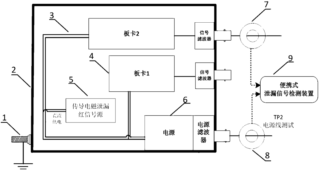
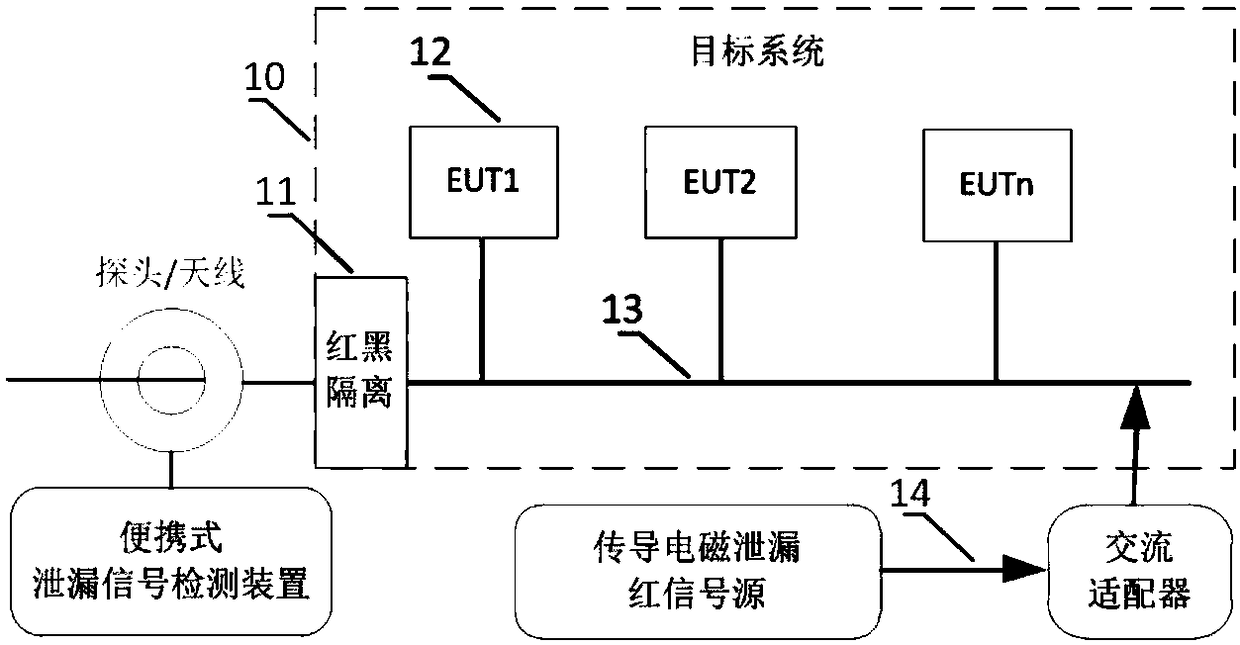
[0039] In one embodiment, the red and black signal isolation capability test environment of a single device is such as figure 1 shown. The power supply cable and communication cable of the device are the main paths for the leakage of electromagnetic information. By actively stimulating the electromagnetic leakage red signal inside the device and performing signal reception tests on the power supply cable and communication cable outside the device, a single The test of the real protection ability of equipment conduction electromagnetic information leakage. Similarly, the conduction electromagnetic information leakage pro


PUM

PropertyMeasurementUnit
Frequencyaaaaaaaaaa

Abstract

The invention discloses a detection method against power conduction electromagnetic leakage. The method comprises that a conduction electromagnetic leakage red signal source generates an electromagnetic leakage red signal for simulating a conduction electromagnetic leakage signal, and the electromagnetic leakage red signal is coupled to a power line of the signal source; and a leakage signal detector receives and analyzes the signal in the reception end. The invention also discloses a detection device against power conduction electromagnetic leakage. The detection device comprises the conduction electromagnetic leakage red signal source and the leakage signal detector; the conduction electromagnetic leakage red signal source generates the electromagnetic leakage red signal for simulating the conduction electromagnetic leakage signal and couples the electromagnetic leakage red signal to the power line of the signal source; and the leakage signal detector receives and analyzes the signalin the reception end. Thus, the conduction leakage protection capability of equipment and system can be detected rapidly, and weak points can be located.

Description


Claims


Application Information

Patent Timeline
Owner CHINA ELECTRONICS TECH CYBER SECURITY CO LTD
Why Eureka
Try Eureka