Automatic lactation-promoting device special for puerperae of obstetrics and gynecology department
An obstetrics and gynecology, automatic technology, used in massage auxiliary products, kneading massage appliances, physical therapy and other directions to achieve the effect of improving prolactin efficiency, simple operation and safe use
- Summary
- Abstract
- Description
- Claims
- Application Information
AI Technical Summary
Problems solved by technology
Method used
Image

Examples
Embodiment 1
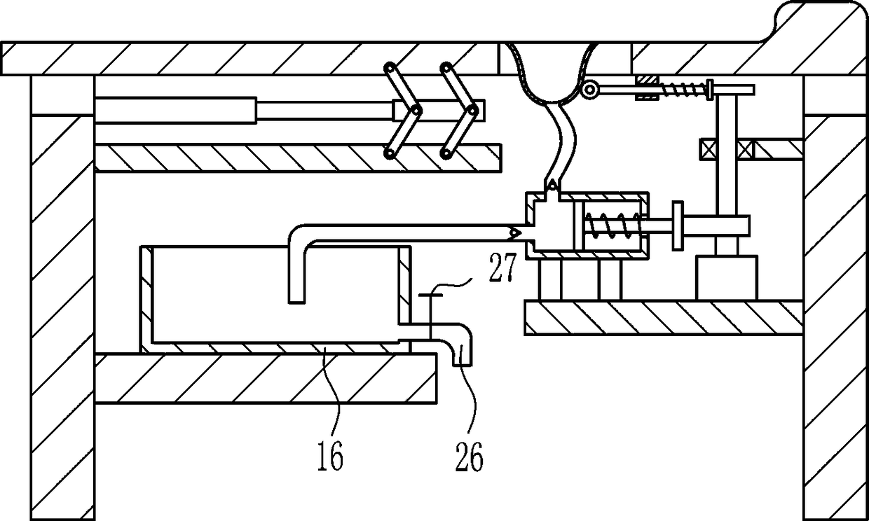
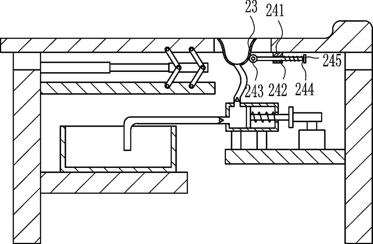
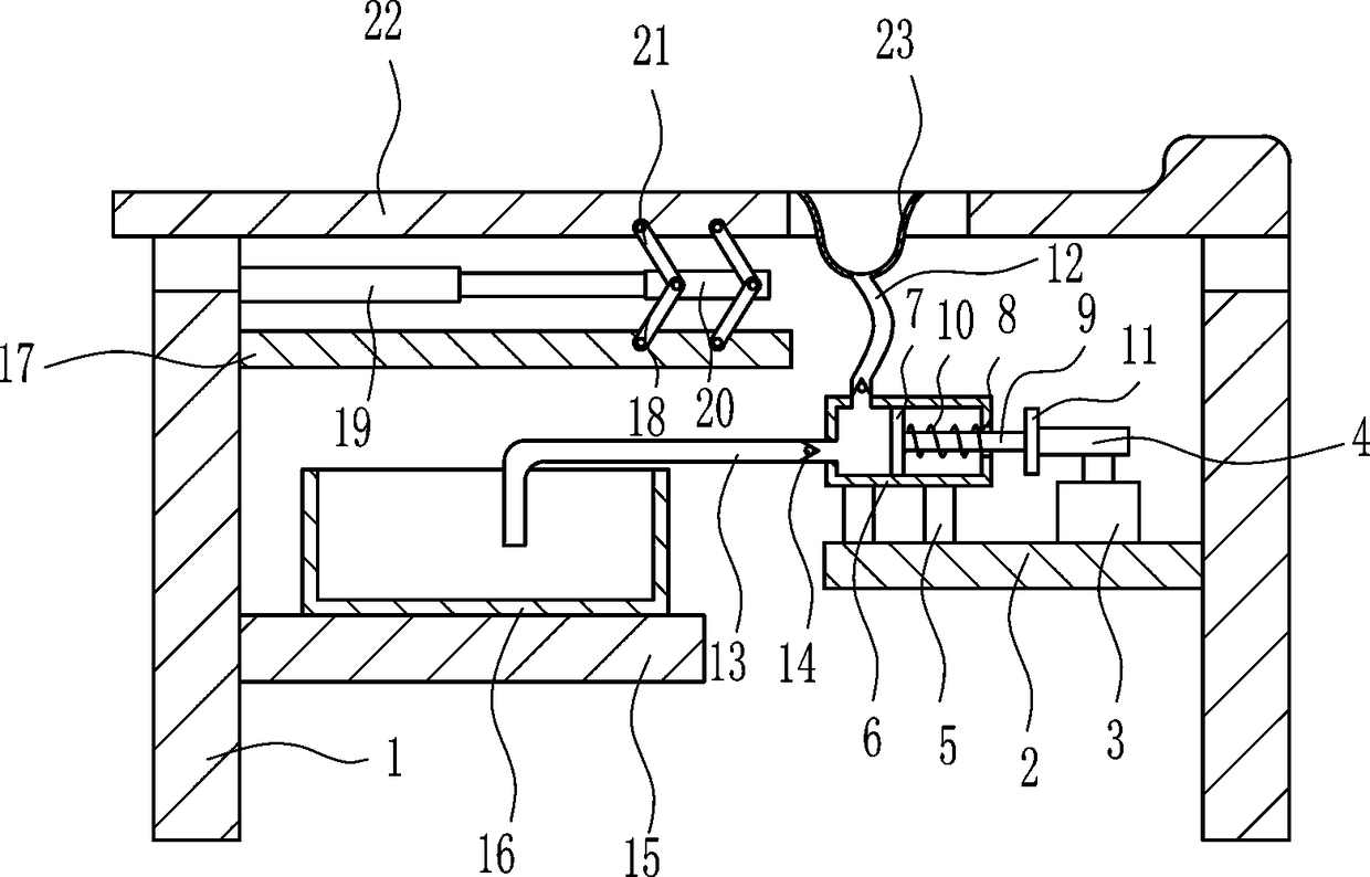
[0027] An automatic lactation device dedicated to obstetrics and gynecology, such as Figure 1-5As shown, it includes a first bracket 1, a second bracket 2, a motor 3, a first cam 4, a first pole 5, an extrusion box 6, an extrusion plate 7, a guide rod 9, a first spring 10, a first Baffle plate 11, first suction pipe 12, second suction pipe 13, one-way valve 14, third support 15, collection box 16, fourth support 17, first connecting rod 18, cylinder 19, fixed plate 20, second connecting rod 21. The bed 22 and the rubber cover 23 are provided with two first brackets 1 on the horizontal plane, a second bracket 2 is fixedly connected to the left side of the first bracket 1 on the right side, and a motor 3 is fixedly connected to the second bracket 2 On the output shaft of the motor 3, there is a first cam 4 that is interference-connected, and on the upper left side of the second support 2, there are two first struts 5 fixedly connected, and on the two first struts 5, there are extr
Embodiment 2
[0029] An automatic lactation device dedicated to obstetrics and gynecology, such as Figure 1-5 As shown, it includes a first bracket 1, a second bracket 2, a motor 3, a first cam 4, a first pole 5, an extrusion box 6, an extrusion plate 7, a guide rod 9, a first spring 10, a first Baffle plate 11, first suction pipe 12, second suction pipe 13, one-way valve 14, third support 15, collection box 16, fourth support 17, first connecting rod 18, cylinder 19, fixed plate 20, second connecting rod 21. The bed 22 and the rubber cover 23 are provided with two first brackets 1 on the horizontal plane, a second bracket 2 is fixedly connected to the left side of the first bracket 1 on the right side, and a motor 3 is fixedly connected to the second bracket 2 On the output shaft of the motor 3, there is a first cam 4 that is interference-connected, and on the upper left side of the second support 2, there are two first struts 5 fixedly connected, and on the two first struts 5, there are ext
Embodiment 3
[0032] An automatic lactation device dedicated to obstetrics and gynecology, such as Figure 1-5 As shown, it includes a first bracket 1, a second bracket 2, a motor 3, a first cam 4, a first pole 5, an extrusion box 6, an extrusion plate 7, a guide rod 9, a first spring 10, a first Baffle plate 11, first suction pipe 12, second suction pipe 13, one-way valve 14, third support 15, collection box 16, fourth support 17, first connecting rod 18, cylinder 19, fixed plate 20, second connecting rod 21. The bed 22 and the rubber cover 23 are provided with two first brackets 1 on the horizontal plane, a second bracket 2 is fixedly connected to the left side of the first bracket 1 on the right side, and a motor 3 is fixedly connected to the second bracket 2 On the output shaft of the motor 3, there is a first cam 4 that is interference-connected, and on the upper left side of the second support 2, there are two first struts 5 fixedly connected, and on the two first struts 5, there are ext
PUM
 Abstract
Description
Claims
Application Information
 - R&D Engineer
- R&D Manager
- IP Professional
- Industry Leading Data Capabilities
- Powerful AI technology
- Patent DNA Extraction
Browse by: Latest US Patents, China's latest patents, Technical Efficacy Thesaurus, Application Domain, Technology Topic.
© 2024 PatSnap. All rights reserved.Legal|Privacy policy|Modern Slavery Act Transparency Statement|Sitemap