Anti-breaking grooving machine for construction site

A technology for construction sites and grooving machines, which can be used in construction, earthmoving machines/shovels, etc., and can solve problems such as uneven hardness and damage to cutting blades.

Pending Publication Date: 2018-08-03
WUXI KONSTANT POWER TECH CO LTD
View PDF0 Cites 0 Cited by
  • Summary
  • Abstract
  • Description
  • Claims
  • Application Information

AI Technical Summary

Problems solved by technology

[0005] Aiming at the deficiencies of the prior art, the present invention provides an anti-interruption groove cutting machine f

Method used


Image

  • Anti-breaking grooving machine for construction site
  • Anti-breaking grooving machine for construction site

Examples


Embodiment Construction

[0021] The following will clearly and completely describe the technical solutions in the embodiments of the present invention with reference to the accompanying drawings in the embodiments of the present invention. Obviously, the described embodiments are only some, not all, embodiments of the present invention. Based on the embodiments of the present invention, all other embodiments obtained by persons of ordinary skill in the art without making creative efforts belong to the protection scope of the present invention.

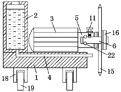
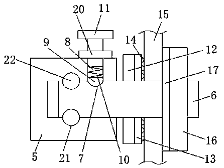
[0022] see Figure 1-2 , the present invention provides a technical solution: an anti-interruption slotting machine for construction sites, including a mounting base plate 1, the lower surface of the mounting base plate 1 is fixedly connected with a support leg 18, and the bottom end of the support leg 18 is fixedly installed with a driving Wheel 19, the upper surface of installation base plate 1 is fixedly connected with water tank 2 and cutting motor 3 respecti


PUM


Abstract

The invention discloses an anti-breaking grooving machine for a construction site. The anti-breaking grooving machine for the construction site comprises an installing bottom plate; a water tank and acutting motor are fixedly connected to the upper surface of the installing bottom plate; a water leaking pipe is fixedly connected in the installing bottom plate; one end of the water leaking pipe communicates with the inner bottom wall of the water tank; and the other end of the water leaking pipe extends to the exterior of the installing bottom plate. The anti-breaking grooving machine for theconstruction site achieves the effect of performing twisting force adjustment on a cutting rotating shaft, when the twisting force borne by the cutting rotating shaft is large, an adjusting rod disengages from the inner wall of an adjusting groove to continue to rotate, and after rotating is performed by a circle, the adjusting rod is connected with the inner wall of the adjusting groove again inan inserted manner; and when the twisting force borne by the cutting rotating shaft is still large, the adjusting rod repeats the above action, at the moment, the installing bottom plate can be pushedbackwards properly, then the cutting rotating shaft can continue to rotate, then the feeding amount is adjusted, and therefore the problem that because the material hardness is not uniform, a cuttingblade is damaged easily is effectively solved.

Description


Claims


Application Information

Patent Timeline
Owner WUXI KONSTANT POWER TECH CO LTD
Why Eureka
Try Eureka