Bayesian model-based dynamic flight time measurement method

A Bayesian model, dynamic flight technology, applied in the direction based on specific mathematical models, calculation models, instruments, etc., can solve problems such as errors

Inactive Publication Date: 2018-08-14
视缘(上海)智能科技有限公司
View PDF0 Cites 0 Cited by
  • Summary
  • Abstract
  • Description
  • Claims
  • Application Information

AI Technical Summary

Problems solved by technology

However, in the prior art, there is still a certain error in the high-precis

Method used


Image

  • Bayesian model-based dynamic flight time measurement method
  • Bayesian model-based dynamic flight time measurement method
  • Bayesian model-based dynamic flight time measurement method

Examples


Embodiment Construction

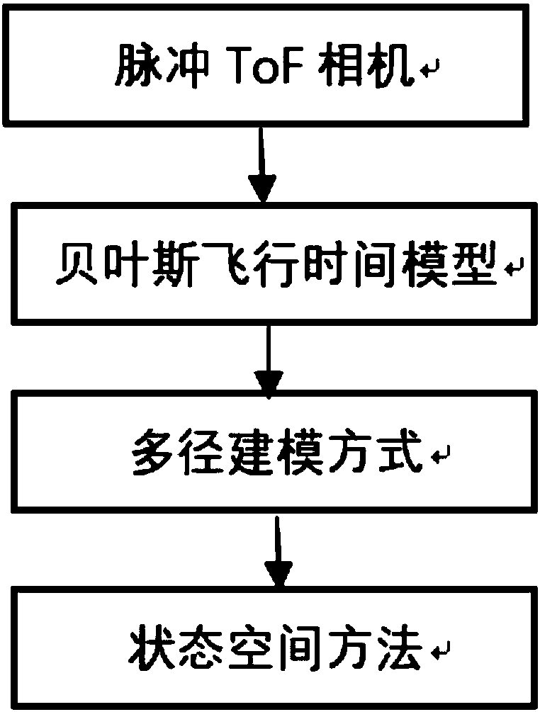
[0044] figure 1 It is a functional block diagram of a dynamic time-of-flight measurement method based on a Bayesian model of the present invention, mainly including a comparison between a static ToF camera and a dynamic ToF camera used in the present invention.

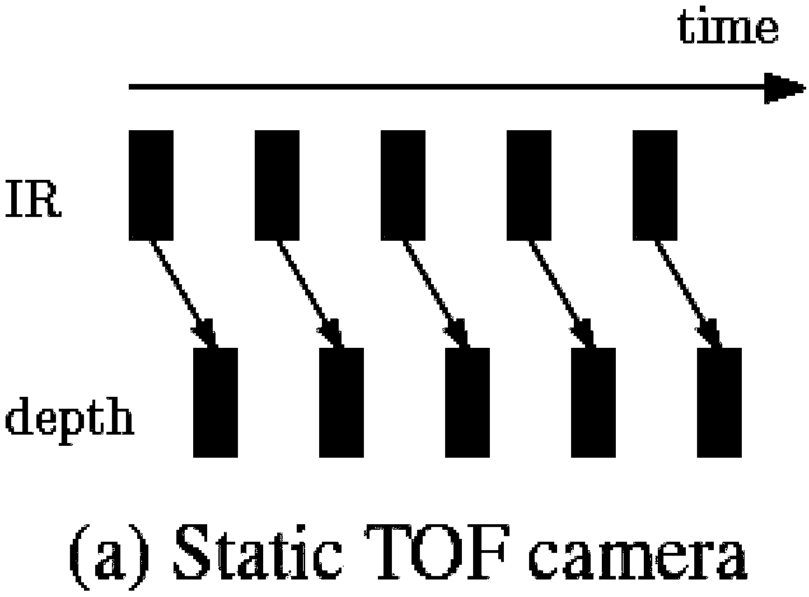
[0045] figure 2 It is a static ToF camera that uses the same measurement method to capture a set of infrared frames in each same time period, and only uses the captured information once to reconstruct the depth in the current time period.

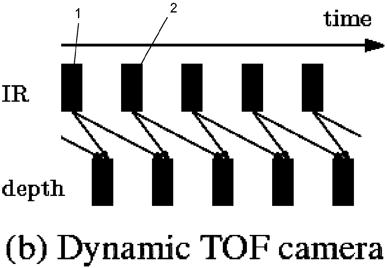
[0046] image 3 It is the dynamic ToF camera of the present invention that integrates multiple time measurements (first indicator box 1 and second indicator box 2) in different time periods using different measurement modes to improve depth accuracy

[0047] Among them, the new perceptual inference framework can use different active measurement modes, as shown in the first indication box 1 and the second indication box 2, using the ability of previous observations and the probabili


PUM


Abstract

The invention provides a Bayesian model-based dynamic flight time measurement method. The method comprises the following steps of S1, selecting a pulse ToF camera; S2, building a Bayesian flight timemodel; S3, building a multipath model; S4, building a state spatial model; and S5, building a steady temporal model. A generative model is built by using motions of the camera and an object as observation values; principle-based Bayesian inference is performed on the model; by shooting multiple frames of infrared images, depth estimation is obtained; a positive measurement mode is designed; supplementary information is collected as time goes on; and by a using a regression tree method, first real-time time integration is demonstrated in low operation and low memory operation. Through the Bayesian model-based dynamic flight time measurement method provided by the invention, the camera is improved in calculation efficiency and information capture; the depth precision is improved in a strongbaseline method; the timeliness and the transformation resistance are achieved; and the system precision is improved.

Description


Claims


Application Information

Patent Timeline
Owner 视缘(上海)智能科技有限公司
Why Eureka
Try Eureka