Multi-cylinder rotary compressor
A technology for a rotary compressor and a compression mechanism, applied in the field of compressors, can solve problems such as unsatisfactory fixing effect, and achieve the effect of improving fixing strength and maintaining core alignment accuracy.
- Summary
- Abstract
- Description
- Claims
- Application Information
AI Technical Summary
Benefits of technology
Problems solved by technology
Method used
Image

Examples
Embodiment 1
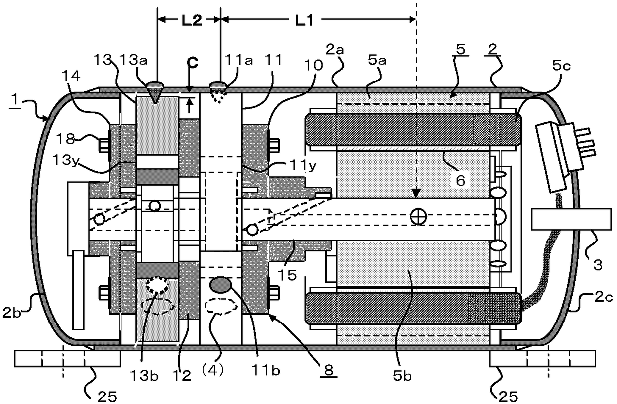
[0046] figure 1 The illustrated twin-cylinder rotary compressor 1 has an electric motor 5 fixed to the inner peripheral portion of the hermetic casing 2 , and a compression mechanism unit 8 driven by the electric motor 5 . The compression mechanism part 8 is composed of the first cylinder 11 and the second cylinder 13, the intermediate partition 12 arranged between the compression chamber 11y and the compression chamber 13y of the above-mentioned cylinder, the main bearing 10 and the auxiliary bearing fixed on the opening ends of the two compression chambers 14. It is composed of a crankshaft 15 that drives the moving parts arranged in the above-mentioned compression chamber and is slidingly fitted with the main bearing 10 and the auxiliary bearing 14. The rotor 5b is fixed on the crankshaft 15.
[0047] The compression mechanism part 8 is pre-precisely aligned with the first compression chamber 11y and the second compression chamber 13y. Thereafter, using the compression chambe
Embodiment 2
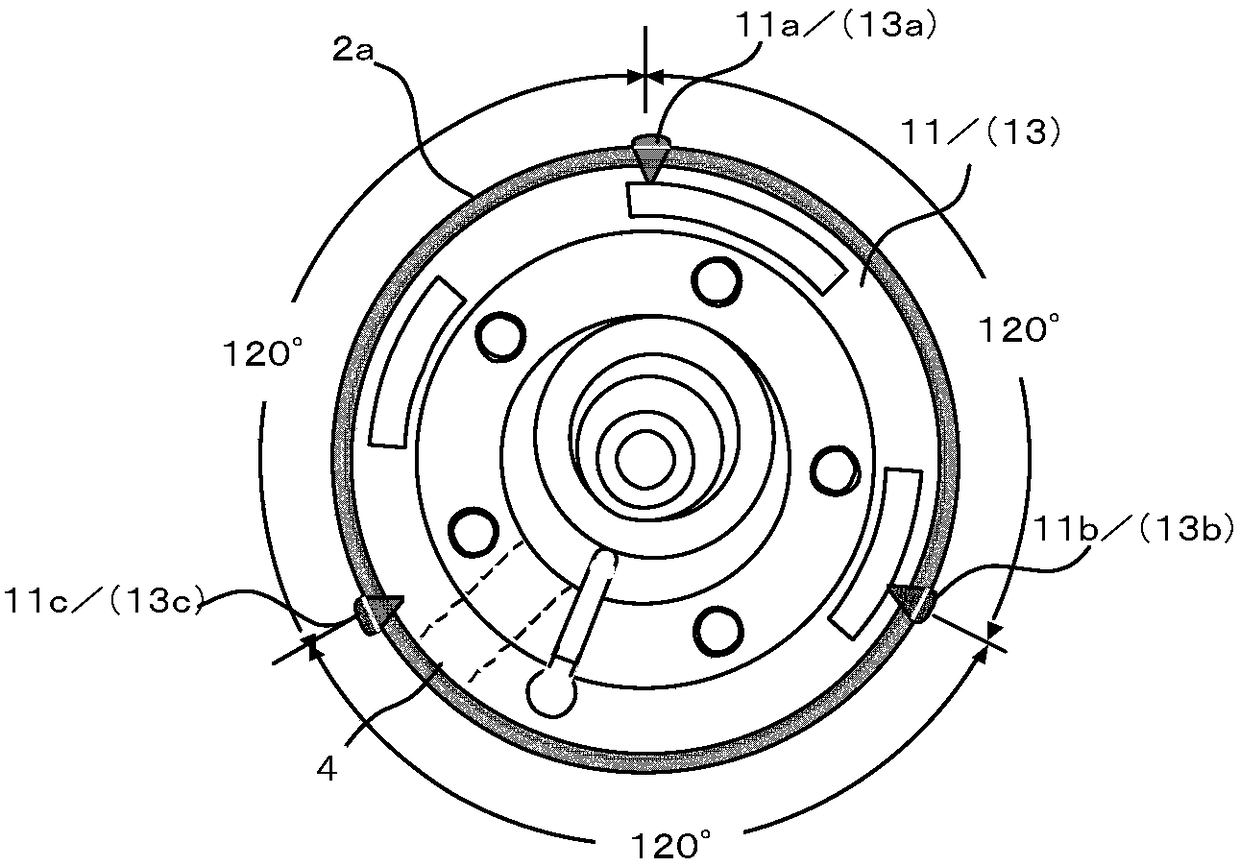
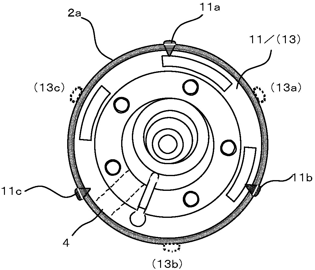
[0062] Example 1 figure 2 The welding points of the first cylinder 11 and the second cylinder 13 are shown, in both cylinders, the welding point angle is the same, however, image 3 In the illustrated embodiment 2, the design is such that the welding points of the second cylinder 13 are arranged almost at the center of the welding points of the first cylinder 11 with respect to the welding points 11a, 11b, 11c of the first cylinder 11 .
[0063] Therefore, in Example 2, each spot is dispersed at 60°. Compared with Example 1, in Example 2, there exists an effect that the welding strength of the compression mechanism part 8 becomes stronger when it applies to the dispersion|distribution of the vibration direction of a compressor.
Embodiment 3
[0065] Figure 4 Among them, the main bearing 10 of the compression mechanism part 8 is used as a reference component, and its outer peripheral part 6 is spot-welded to the inner peripheral part of the cylindrical case 2a to fix it. And it fixes by 3 spot welding the outer peripheral part of the intermediate|middle partition plate 12 which is an auxiliary part, and the inner peripheral part of the cylindrical case 2a. Therefore, the welding points of the main bearing 10 are 10a, 10b, 10c, 10d, (10e), (10f), and the welding points of the intermediate partition plate 12 are 12a, 12b, (12c).
[0066] The intervals between the welding points of the main bearing 10 and the intermediate partition 12 are 60° and 120° respectively, and among the welding points of the main bearing 10 as a reference component, three are with the intermediate partition 12 as an auxiliary component. The solder joints are consistent. As in the first embodiment, the outer diameter of the intermediate partiti
PUM
 Abstract
Description
Claims
Application Information
 - R&D Engineer
- R&D Manager
- IP Professional
- Industry Leading Data Capabilities
- Powerful AI technology
- Patent DNA Extraction
Browse by: Latest US Patents, China's latest patents, Technical Efficacy Thesaurus, Application Domain, Technology Topic.
© 2024 PatSnap. All rights reserved.Legal|Privacy policy|Modern Slavery Act Transparency Statement|Sitemap