Plastic part processing device

A processing device and technology of plastic parts, applied in the field of plastic plate processing, can solve the problem of non-adjustable width of the dust removal wipe head, and achieve the effect of enhancing the cleaning effect

Inactive Publication Date: 2018-08-31
宁波得晴电器科技有限公司
View PDF0 Cites 2 Cited by
  • Summary
  • Abstract
  • Description
  • Claims
  • Application Information

AI Technical Summary

Benefits of technology

This invention relates to an apparatus used during manufacturing processes or production lines. It includes various features such as branches, pivoted arms, movable parts like fans, shafts, etc., along with a special system called a process table where different materials may be processed simultaneously. These improvements help improve product quality while reducing costs associated therewith.

Problems solved by technology

This technical problem addressed in this patented text relates to improving the efficiency at which layers of plastisol material (plaster) coatings onto platy materials like polyethylene terephthalate (PET), vinyl chloride resin(VCR)) boards made by extrusion molding processes. To ensure proper adhesion without any unwanted particles being present, these PENGASIS® brand products require periodic cleaning of their plasma panel's surface. Current methods involve removing excessive amounts of abrasives manually, but they may also cause damage if too much pressure is applied. There has been an effort towards developing improved ways to efficiently clean the plasmas used for producing films.

Method used


Image

  • Plastic part processing device
  • Plastic part processing device
  • Plastic part processing device

Examples


Embodiment 1

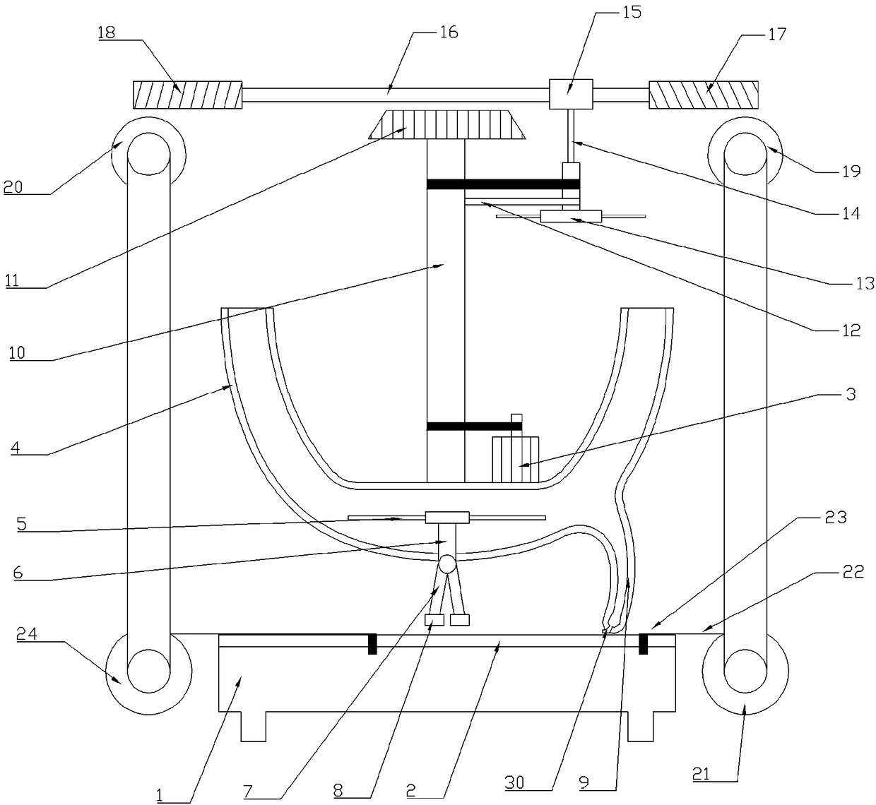
[0020] The embodiment is basically as attached figure 1 As shown: a plastic parts processing device, including a processing table 1 and a drive unit. In this embodiment, the drive unit is set as a motor 3, and a U-shaped tube 4 is arranged above the processing table 1, and a fan 5 is connected to the U-shaped tube 4 for rotation. , the lower end of the fan 5 is fixedly connected with a vertical rod 6 passing through the U-shaped pipe 4, and the vertical rod 6 is slidingly connected with the U-shaped pipe 4. When the fan 5 rotates, the vertical rod 6 can slide downward due to the wind force, and the vertical rod 6 The lower end of the U-shaped tube 4 is hingedly connected with several swing arms 7, the bottom of the swing arm 7 is provided with a dust removal wiper 8 for removing dust, the right side of the U-shaped tube 4 is provided with a branch pipe 9, and the tail end of the branch pipe 9 Several air outlets 30 are provided. A rotating shaft 10 is arranged above the U-shaped

Embodiment 2

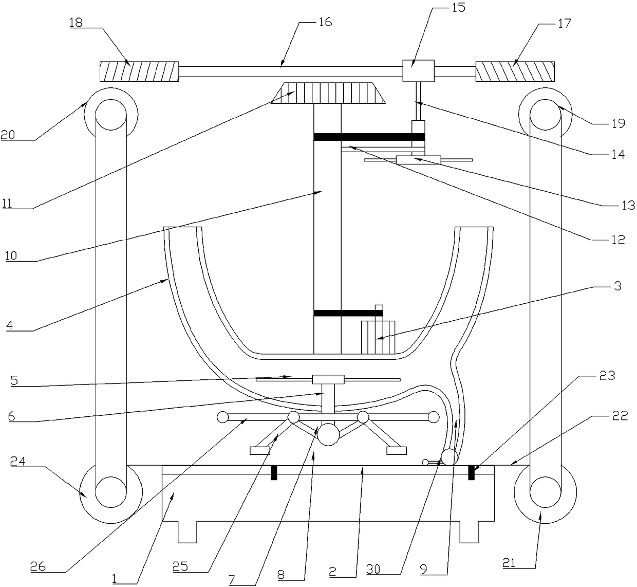
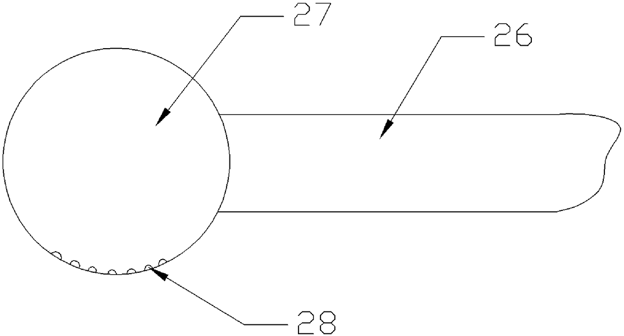
[0025] like figure 2 , image 3 and Figure 4 As shown, the difference between the present embodiment and the first embodiment is that the swing arm 7 at the lower end of the vertical bar 6 is M-shaped and includes four connecting rods 25 that are hinged to each other. The lower end of vertical bar 6 is also provided with slide rail 26, and two apexes of swing arm 7 are hinged on slide rail 26, and swing arm 7 middle parts are hingedly connected with vertical bar 6; The two ends of slide rail 26 are provided with water polo 27, as Figure 4 As shown, some nozzle holes 28 are also arranged on the water polo 27 , when the water polo 27 is squeezed, the water flow will flow out from the nozzle holes 28 .

[0026] During specific implementation, the swing arm 7 is set to an M shape, and the apex of the swing arm 7 is hinged on the slide rail 26. As the wind force size of the fan 5 in the U-shaped pipe 4 changes, the two apexes of the swing arm 7 are in the chute. Slide left and r


PUM


Abstract

The invention belongs to the technical field of plastic plate processing, in particular to a plastic part processing device. The plastic part processing device comprises a processing table and a driving unit. A U-shaped pipe is arranged above the processing table, and the inner part of the U-shaped pipe is connected with a fan. The lower end of the fan is connected with a vertical rod, a swingingarm is hinged on the vertical rod, and a dedusting brush head is arranged at the bottom of the swinging arm. A branch pipe is arranged on one side of the U-shaped pipe, and a rotation shaft is arranged above the U-shaped pipe and is connected with the driving unit. A main worm wheel is arranged at the upper end of the rotation shaft, and a cross rod is connected on the rotation shaft and is connected with a ceiling fan. The ceiling fan is connected with the rotation shaft, and a connecting rod is arranged at the upper end of the ceiling fan. A sleeve is arranged at the upper end of the connecting rod, and a cross shaft is arranged in the sleeve. The two ends of the cross shaft are respectively connected with a first worm and a second worm. A first worm wheel belt is connected with a scrubbing roller, the scrubbing roller is twined with a tape, and a scraping bar is arranged on the tape. A film unfolding roller is arranged on the processing table. According to the technical scheme, theplastic part processing device can fast clean the surface of a plastic plate and mulching a film.

Description


Claims


Application Information

Patent Timeline
Owner 宁波得晴电器科技有限公司
Why Eureka
Try Eureka