Hugger fan twist-lock mechanism and method

a technology of twist-lock mechanism and fan, which is applied in the direction of washstands, scaffold accessories, lighting support devices, etc., can solve the problems of increasing the requirement of installation personnel having to maintain their balance, difficult mounting of ceiling fans, and tedious motors

Active Publication Date: 2013-04-16
CHIEN LUEN INDS
View PDF16 Cites 9 Cited by
  • Summary
  • Abstract
  • Description
  • Claims
  • Application Information

AI Technical Summary

Benefits of technology

The technical effect of this patented mechanism for attaching a ceilings-mounted panel with a ceiled fan motor' housings without requiring any tools or parts needed are improved efficiency and ease of installation compared to traditional ways by reducing time required during assembly process.

Problems solved by technology

This patented problem addressed in this patents relates to installing ceilage fans due to difficulties attaching them safely when they shouldn’t. Current methods involve holding down multiple tools at once, making assembly process longer than necessary. Additionally, there may be safety concerns associated with the use of screw-type fastening devices because they can easily lose themselves. Therefore, an objective solution needs to address both issues simultaneover effectively.

Method used


Image

  • Hugger fan twist-lock mechanism and method
  • Hugger fan twist-lock mechanism and method
  • Hugger fan twist-lock mechanism and method

Examples


Embodiment Construction

[0030]Before explaining the disclosed embodiments of the present invention in detail it is to be understood that the invention is not limited in its applications to the details of the particular arrangements shown since the invention is capable of other embodiments. Also, the terminology used herein is for the purpose of description and not of limitation.

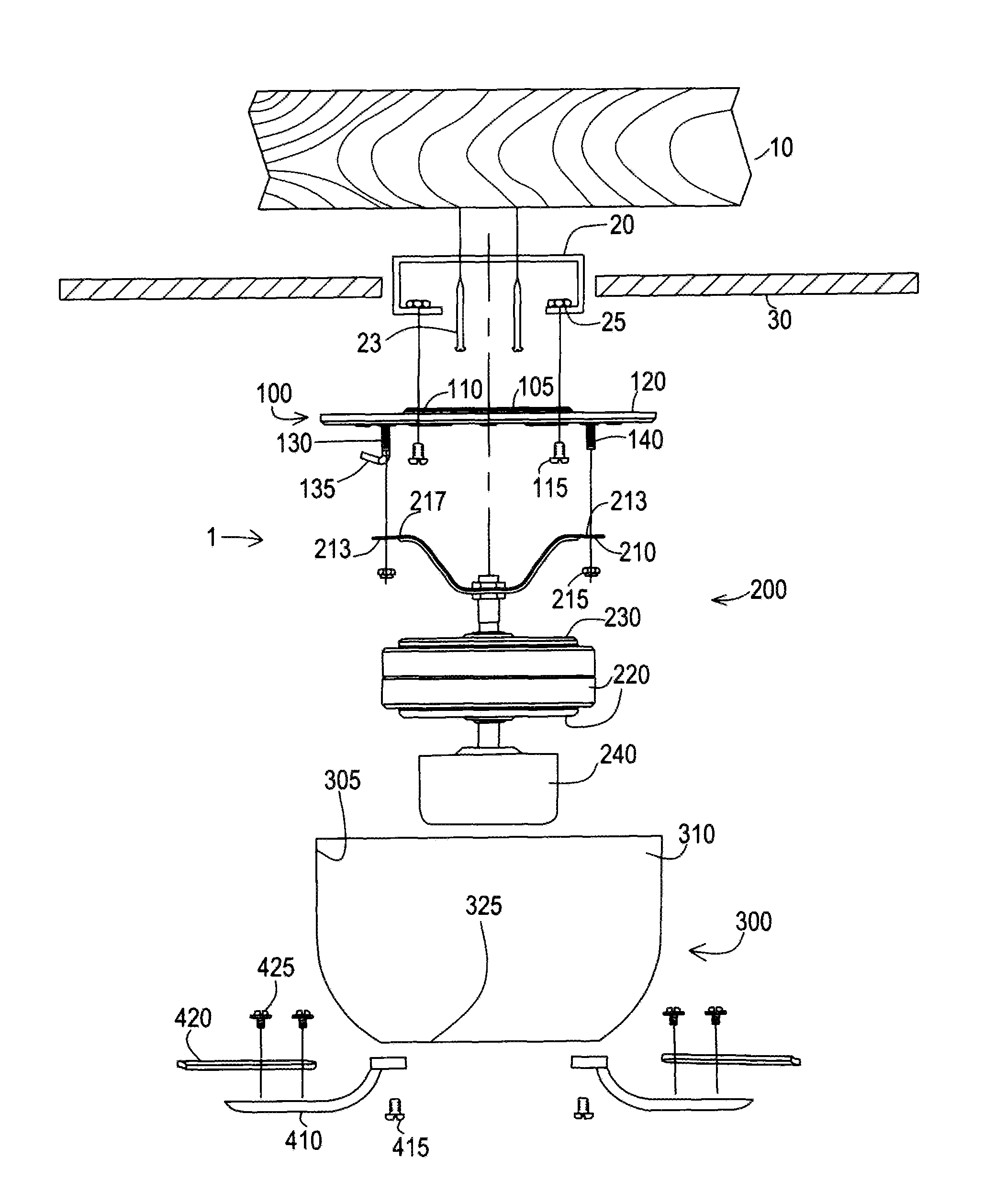
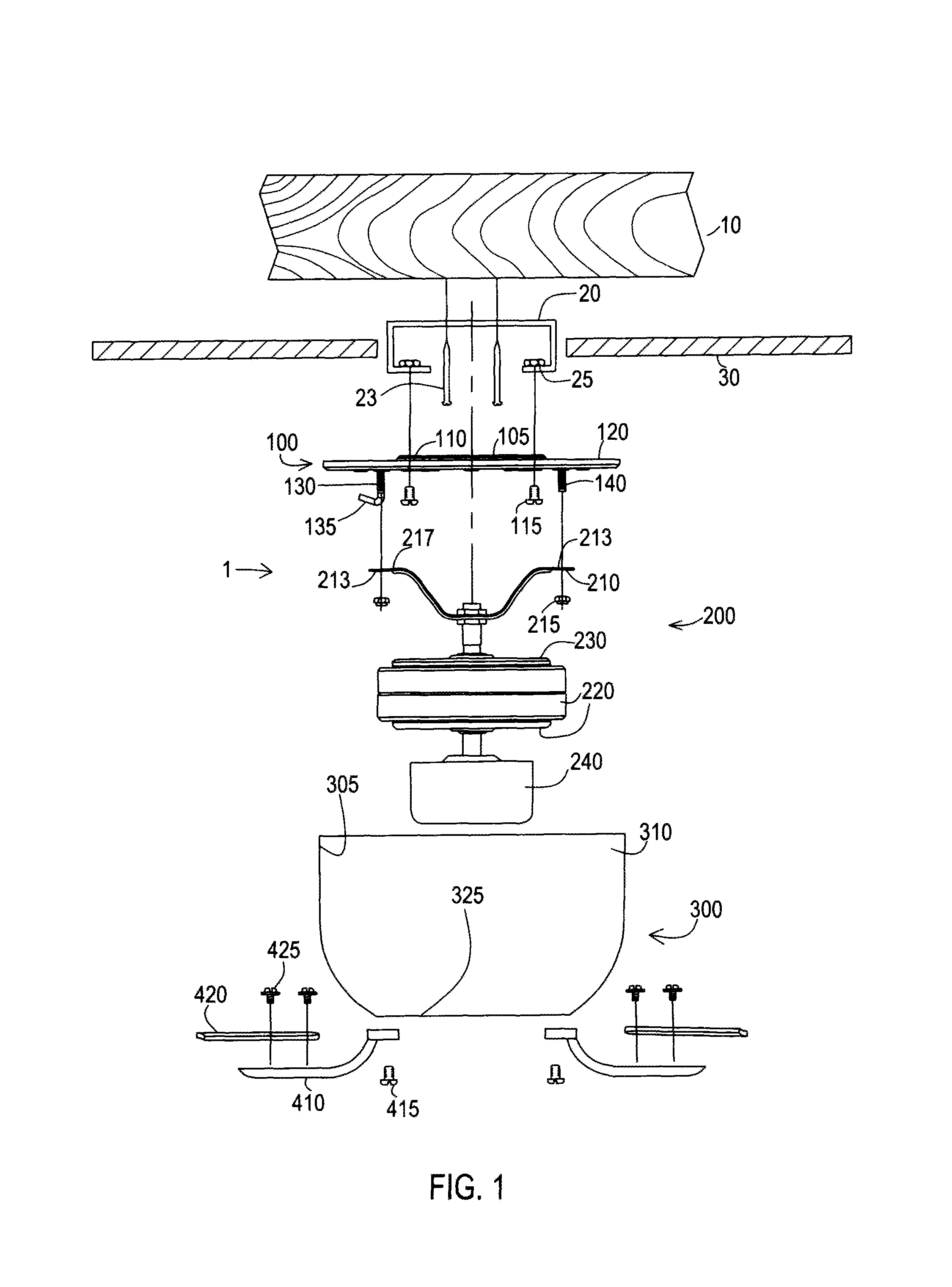
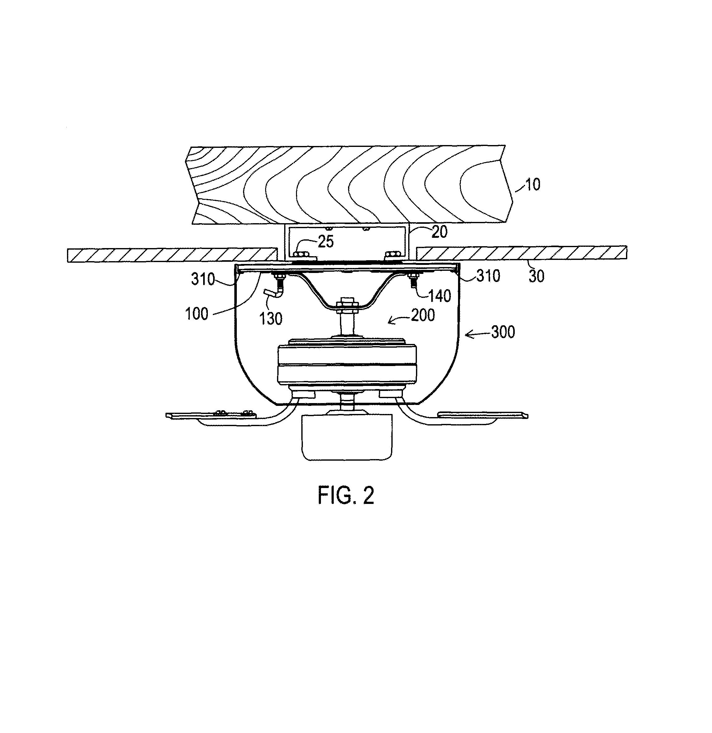
[0031]A list of the components will now be described.[0032]1. twist lock mechanism[0033]10. Ceiling joist[0034]20. Ceiling mounted outlet box[0035]23. Joist mounting fasteners (screws)[0036]25. mounting (female fasteners) nuts[0037]30. Ceiling drywall[0038]100. novel mounting plate[0039]105. raised middle portion[0040]110. mount holes to attach to outlet box[0041]115. screw fasteners attach plate to outlet box[0042]120. longitudinal oval slots spaced about perimeter of plate[0043]130. downwardly extending hook on male coupler fastener[0044]135. hook end[0045]140. male coupler fastener[0046]200. fan components[0047]210. hang bracket[004


PUM


Abstract

Mechanisms, devices, apparatus, systems and methods of installing ceiling fan motor housings to ceiling mounted plates without using loose fasteners such as screws, and the like. A plate having a plurality of slots about the perimeter can be pre-mounted to a ceiling. A motor housing having clips on interior perimeter edges of the base can be positioned so that the clips are inserted into the slots. Next, the motor housing can be twisted clockwise until the clips lock to the slots allowing the ceiling fan motor to be hung without any loose fasteners. The twist-lock eliminates unsightly fasteners, such as screws underneath the housing, quickens installation time, and is easier and safer than traditional ceiling fan installation techniques.

Description


Claims


Application Information

Patent Timeline
Owner CHIEN LUEN INDS
Why Eureka
Try Eureka