Power flow obtaining method applicable to AC and DC system

An acquisition method, AC and DC technology, applied in AC network circuits, power transmission AC networks, AC networks with the same frequency from different sources, etc., can solve problems such as difficult convergence and falling into local optimal solutions

Inactive Publication Date: 2018-09-28
ELECTRIC POWER RESEARCH INSTITUTE OF STATE GRID QINGHAI ELECTRIC POWER COMPANY +2
View PDF2 Cites 7 Cited by
  • Summary
  • Abstract
  • Description
  • Claims
  • Application Information

AI Technical Summary

Problems solved by technology

[0003] Aiming at the above defects or improvement needs of the prior art, the present invention proposes a power flow acquisition method suitable for AC and DC systems, aiming to effe

Method used


Image

  • Power flow obtaining method applicable to AC and DC system
  • Power flow obtaining method applicable to AC and DC system
  • Power flow obtaining method applicable to AC and DC system

Examples


example

[0171] Figure 8 It is the system diagram of the selected IEEE14 node test system, which is used as an example to illustrate. In the example, a converter is added to node 1 and node 4 respectively, and a DC line is added between them to form an AC-DC power system.

[0172] 1. Collect the conventional technical parameters of the AC-DC interconnected grid, and calculate the initial power flow state of the grid.

[0173] Such as Figure 8 The AC and DC power system shown includes the number of AC nodes N bAC =14, the number of AC lines N lAC =20, the number of converter stations N cv =2, the number of DC system nodes N bDC =2, the total number of DC system lines N lDC =1, AC node parameters are shown in Table 1, AC line parameters are shown in Table 2, generator parameters are shown in Table 3, converter parameters are shown in Table 4, DC node parameters are shown in Table 5, and DC line parameters are shown in Table 6. In addition, considering the actual operation situation


PUM


Abstract

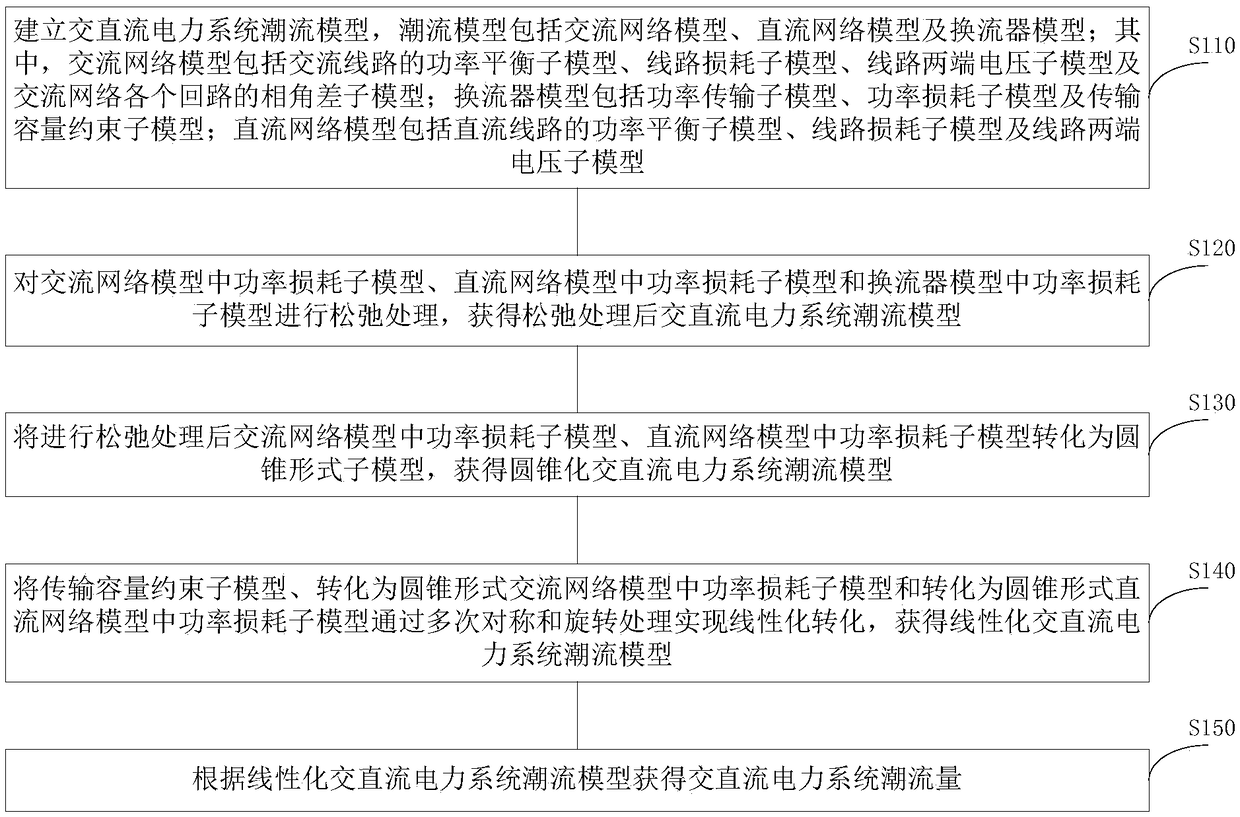
The invention discloses a power flow obtaining method applicable to an AC and DC system. The power flow obtaining method comprises the steps of: firstly, establishing an AC and DC power system power flow model including an AC network model, a DC network model and a converter model, then, relaxing the AC and DC power system power flow model to a second-order cone form by adopting a cone relaxationtechnology, and finally, on this basis, obtaining a piecewise linearization AC and DC power system power flow model according to a second-order cone linearization method, wherein the linearization precision can be adjusted through a zooming method and changing of a piecewise number index. According to the power flow obtaining method applicable to the AC and DC system disclosed by the invention, the cone relaxation technology and the second-order cone linearization technology are adopted; the original non-convex nonlinear AC and DC power flow equation is converted into the convex piecewise linearization form; the operation economy of the whole AC and DC system can be improved; and simultaneously, the power flow obtaining method is also more suitable for processing all kinds of operation optimization problems having relatively high timeliness requirements in the power system.

Description


Claims


Application Information

Patent Timeline
Owner ELECTRIC POWER RESEARCH INSTITUTE OF STATE GRID QINGHAI ELECTRIC POWER COMPANY
Why Eureka
Try Eureka