Power conversion circuit and control method thereof

A technology for converting circuits and control methods, applied in power factor control, AC motor control, control systems, etc., can solve problems such as low motor power factor, low input power factor, large current harmonics, etc., and achieve power factor improvement. Effect

Active Publication Date: 2018-11-02
AUX AIR CONDITIONING LTD BY SHARE LTD
View PDF4 Cites 0 Cited by
  • Summary
  • Abstract
  • Description
  • Claims
  • Application Information

AI Technical Summary

Benefits of technology

This patented technology improves how much energy can be converted into electrical work compared with traditional methods like resistive heating or AC induction motors. By measuring this ratio between two different values - called Q axis (the electric force) and V axes (voltage).

Problems solved by technology

This patents describes different methods or techniques related to controlling the operation of motors such as synchronous generators. These include phase locked loop systems (PLL's). However, these conventional solutions suffer issues like instabilities caused by variations in loading impedances due to factors including temperature changes over time. To address this issue, there has been proposed various approaches based upon specific mathematical relationships between certain variables called fuzzy rules.

Method used


Image

  • Power conversion circuit and control method thereof
  • Power conversion circuit and control method thereof
  • Power conversion circuit and control method thereof

Examples


Embodiment Construction

[0049] Reference will now be made in detail to the exemplary embodiments, examples of which are illustrated in the accompanying drawings. When the following description refers to the accompanying drawings, the same numerals in different drawings refer to the same or similar elements unless otherwise indicated. The implementations described in the following exemplary examples do not represent all implementations consistent with the present invention. Rather, they are merely examples of apparatuses and methods consistent with aspects of the invention as recited in the appended claims.

[0050] The terminology used in the present invention is for the purpose of describing particular embodiments only and is not intended to limit the invention. As used herein and in the appended claims, the singular forms "a", "the", and "the" are intended to include the plural forms as well, unless the context clearly dictates otherwise. It should also be understood that the term "and / or" as used


PUM


Abstract

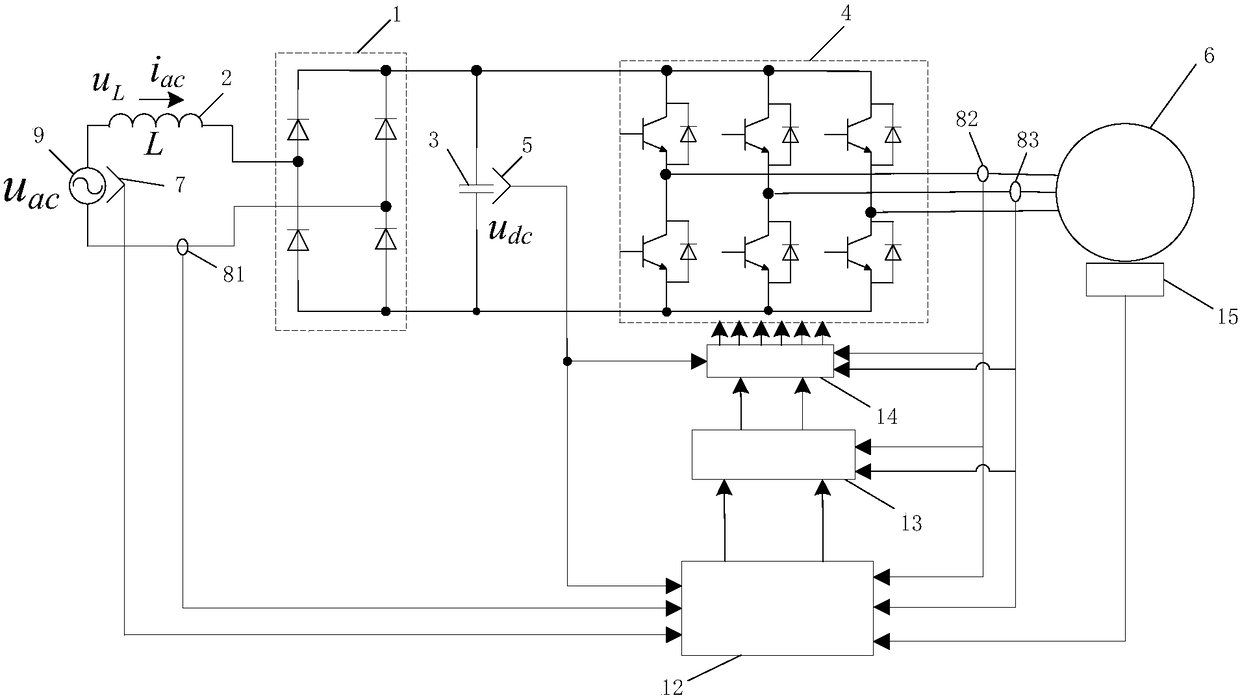
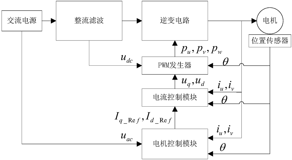
The invention discloses a power conversion circuit, comprising a rectifier module (1), an inductor (2), a capacitor (3), and an inverter circuit (4), wherein the inverter circuit (4) is connected withthe motor (6); the motor control module (12), the current control module (13) and the PWM modulation module (14)are connected in sequence; the voltage detection module (5) is disposed on the capacitor (3), and is connected to the motor control module (12); the first current sensor (81) is connected in series with the alternating current power source (9), and connected to the motor control module(12); and the motor control module (12) determines the improved q-axis torque current reference value Iq_Ref_g according to the alternating current iac and the bus voltage udc. The invention has thebeneficial effects that the change rules of the input current and the input voltage are the same by determining the q-axis torque current reference value Iq_Ref, that is, the power factor of the powerconversion circuit is improved.

Description


Claims


Application Information

Patent Timeline
Owner AUX AIR CONDITIONING LTD BY SHARE LTD
Why Eureka
Try Eureka