Guided mode resonance filter
A guided-mode resonance and filter technology, applied in the field of optical communication, can solve the problems of unfavorable popularization and application of guided-film resonant filters, increase the difficulty of filter manufacturing process, etc., and achieve the effect of simple structure and flexible design.
- Summary
- Abstract
- Description
- Claims
- Application Information
AI Technical Summary
Problems solved by technology
Method used
Image

Examples
Embodiment 1
[0042] Embodiment 1, the guided mode resonant filter proposed by the present invention includes:
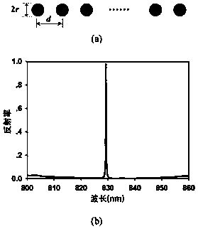
[0043] Identical dielectric rods uniformly distributed in a single layer, such as figure 1 as shown in (a);
[0044] Among them, the cross-sectional radius of the dielectric rod is r, and the distance between the dielectric rods is d. The change of both will affect the size of the resonance wavelength λ. The smaller d is, the smaller the resonance wavelength λ will be. The change of r will affect the equivalent of the structure. Refractive index, and the change of equivalent refractive index will cause the change of resonance wavelength λ); n is the dielectric constant of the dielectric rod, n o It is the dielectric constant of the medium around the dielectric rod, and both satisfy n>n o .
[0045] If the layer of dielectric column structure is equivalent to a layer of uniform dielectric waveguide, then the thickness of the waveguide layer is 2r, and its equivalent refractive ind
Embodiment 2
[0051] Embodiment 2, the guided mode resonant filter proposed by the present invention includes:
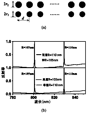
[0052]Multi-layer dielectric rods; wherein, the dielectric constants of the dielectric rods are n, and the dielectric rods are distributed in the dielectric constant of n o In the medium, both satisfy n>n o ; Dielectric rods located in the same layer have the same cross-sectional radius r, and they are evenly distributed, that is, the spacing d is the same; Dielectric rods located in different layers have different cross-sectional radii, thereby achieving multiple different resonance wavelengths λ; each layer of dielectric rods has the same The spacing d and layer spacing h.
[0053] In this embodiment, when the number of layers of the dielectric rod is 2, the structure of the guided mode resonant filter is as follows figure 2 (a) shown. Among them, the radius of the first layer of dielectric rod is r 1 =105nm, the radius of the second layer of dielectric rod is r 2 =110nm, ea
PUM
| Property | Measurement | Unit |
|---|---|---|
| Spacing | aaaaa | aaaaa |
| Radius | aaaaa | aaaaa |
| Bandwidth | aaaaa | aaaaa |
Abstract
Description
Claims
Application Information
 - R&D Engineer
- R&D Manager
- IP Professional
- Industry Leading Data Capabilities
- Powerful AI technology
- Patent DNA Extraction
Browse by: Latest US Patents, China's latest patents, Technical Efficacy Thesaurus, Application Domain, Technology Topic.
© 2024 PatSnap. All rights reserved.Legal|Privacy policy|Modern Slavery Act Transparency Statement|Sitemap