Novel clothes air-drying device

A new type of bottom frame technology, which is applied in the direction of washing devices, household clothes dryers, sports accessories, etc., can solve the problems of single function and slow drying speed of clothes, and achieve the effect of good effect, accelerated drying and convenient movement

Inactive Publication Date: 2018-12-07
郭铁映
View PDF7 Cites 0 Cited by
  • Summary
  • Abstract
  • Description
  • Claims
  • Application Information

AI Technical Summary

Benefits of technology

This innovation describes an improved version that makes it easier or more efficient than traditional methods like iron bars when doing regular laundry tasks on floors without getting tired out too much time waiting before going back home again afterward.

Problems solved by technology

The technical problem addressed by this patented technology relates to improving clothing drier devices that work for household use with slower speeds compared to older designs.

Method used


Image

  • Novel clothes air-drying device
  • Novel clothes air-drying device
  • Novel clothes air-drying device

Examples


specific Embodiment approach 1

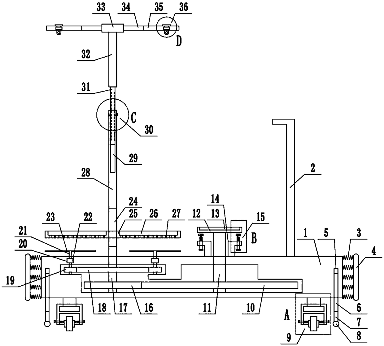
[0028] Combine below figure 1 , 2 , 3, 4, 5, 6, and 7 illustrate this embodiment. The present invention relates to a household tool, more specifically a new clothes drying device, including a chassis 1, an armrest 2, a spring 3, and a protective pad 4 , threaded hole 5, threaded rod one 6, straight rod 7, support frame 8, wheel mechanism 9, gear one 10, shaft one 11, circular plate 12, anti-skid pad 13, support plate 14, extrusion mechanism two 15, gear two 16. Shaft 2 17, Gear 3 18, Gear 4 19, Third Step Hole 1 20, Shaft 3 21, Collar 1 22, Fan Blade 23, Threaded Rod 2 24, Disc Plate 25, Groove 26, Through Hole 27 . The utility model can be used by people for exercising, and can accelerate drying of clothes while exercising. The device is convenient to move, convenient to place socks, and has a good effect of drying clothes.

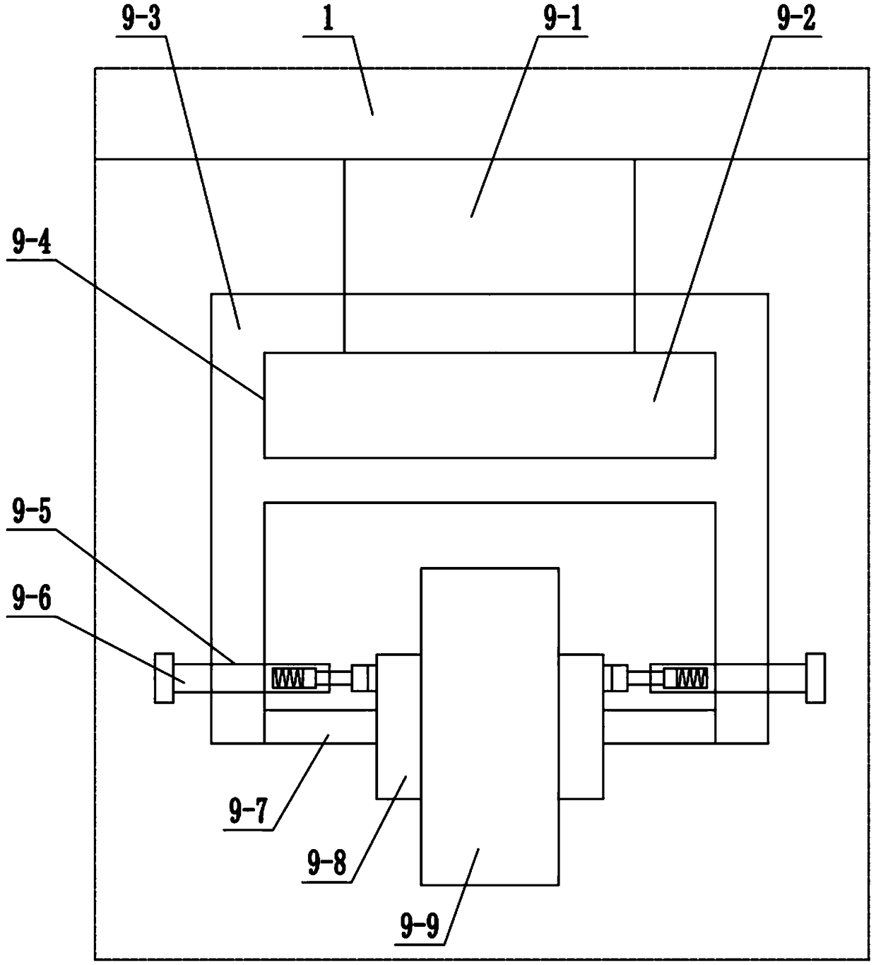
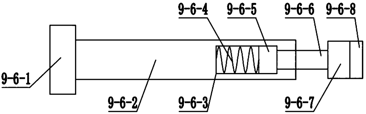
[0029]Wheel mechanism 9 comprises support 9-1, circular block 9-2, wheel frame 9-3, stepped groove-9-4, threaded through hole-9-5, extruding mechanism-9

specific Embodiment approach 2

[0035] Combine below figure 1 , 2 , 3, 4, 5, 6, and 7 illustrate this embodiment, and this embodiment further describes Embodiment 1, and the number of said spring 3 is multiple.

specific Embodiment approach 3

[0036] Combine below figure 1 , 2 , 3, 4, 5, 6, and 7 illustrate this embodiment, and this embodiment further describes Embodiment 1, and the material of the protective pad 4 is rubber.


PUM


Abstract

The invention relates to a domestic tool, in particular to a novel clothes air-drying device. The device can be used for a user to take exercise and use, cloth air-drying can be promoted while exercising, and the device is convenient to move, facilitates sock placement and has a good cloth air-drying effect. A gear I is movably arranged in a bottom frame through a shaft I, the shaft I is fixedly connected with a round plate, an anti-slip pad is arranged on the round plate, a supporting plate is fixed to the bottom frame, and an extruding mechanism II is in threaded connection with the supporting plate. A gear II and a gear III are both installed in the bottom frame through shafts II, a gear IV is installed in the bottom frame through a shaft III, the shaft III penetrates through a three-stage stepped hole I, the three-stage stepped hole I is formed in the bottom frame, a lantern ring I is movably arranged in the three-stage stepped hole I, the shaft III is fixedly connected with the lantern ring I, and fan blades are installed on the shaft III. The lower end of a threaded rod II is connected with the shaft II, the upper end of the threaded rod II is connected with a straight rod, adisc plate is in threaded connection with the threaded rod II, and grooves and holes are both formed in the disc plate.

Description


Claims


Application Information

Patent Timeline
Owner 郭铁映
Why Eureka
Try Eureka