Method and system for stabilizing power grid

A grid and stabilization technology, applied in the field of electric power, can solve the problem that the low-voltage side power distribution room cannot be accurately cut off, and achieve the effect of stabilizing the grid.

Active Publication Date: 2018-12-07
CHNA ENERGY INVESTMENT CORP LTD +2
View PDF4 Cites 0 Cited by
  • Summary
  • Abstract
  • Description
  • Claims
  • Application Information

AI Technical Summary

Problems solved by technology

[0006] The embodiment of the present invention provides a method and system for stabilizing the power grid, so as to at least solve the technical problem in

Method used


Image

  • Method and system for stabilizing power grid
  • Method and system for stabilizing power grid
  • Method and system for stabilizing power grid

Examples


Embodiment Construction

[0024] In order to enable those skilled in the art to better understand the solutions of the present invention, the following will clearly and completely describe the technical solutions in the embodiments of the present invention in conjunction with the drawings in the embodiments of the present invention. Obviously, the described embodiments are only It is an embodiment of a part of the present invention, but not all embodiments. Based on the embodiments of the present invention, all other embodiments obtained by persons of ordinary skill in the art without making creative efforts shall fall within the protection scope of the present invention.

[0025] It should be noted that the terms "first" and "second" in the description and claims of the present invention and the above drawings are used to distinguish similar objects, but not necessarily used to describe a specific sequence or sequence. It is to be understood that the data so used are interchangeable under appropriate cir


PUM


Abstract

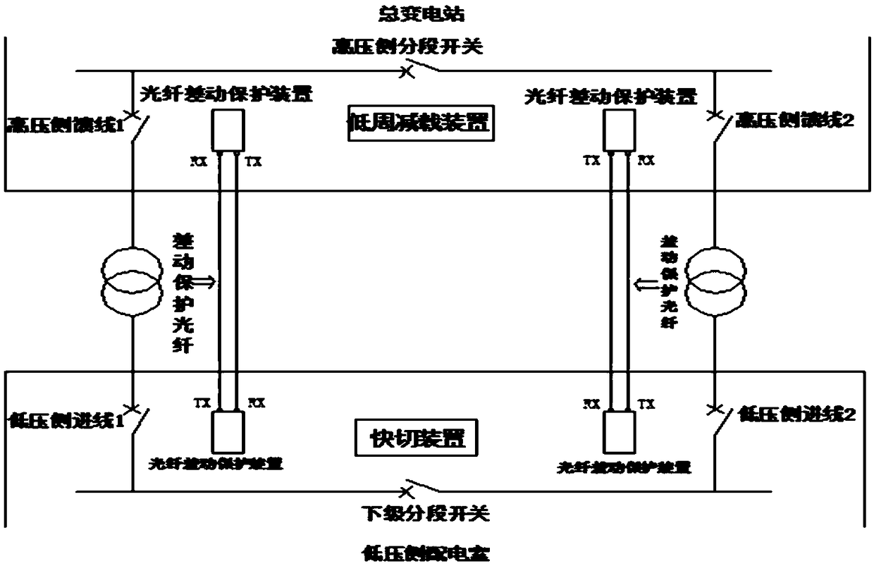
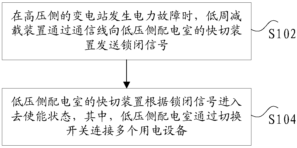
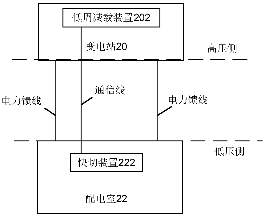
The invention discloses a method and a system for stabilizing a power grid. The method includes the following steps: when a power failure occurs in a substation on the high-voltage side, a low-cycle load shedding device sends a locking signal to a fast switching device of a low-voltage side distribution room through a communication line; and the fast switching device of the low-voltage side distribution room enters a disenabled state according to the locking signal, wherein the low-voltage side distribution room is connected with multiple pieces of electric equipment through a change-over switch, the low-voltage side and the high-voltage side are connected by a pair of power feeders, and the communication line is used to transmit the locking signal. The technical problem in the related technology that the low-voltage side distribution room cannot be accurately switched off when the cycle wave of the power grid failure system collapses is solved, and the technical effects of power consumption balancing and power grid stabilizing are achieved.

Description


Claims


Application Information

Patent Timeline
Owner CHNA ENERGY INVESTMENT CORP LTD
Why Eureka
Try Eureka