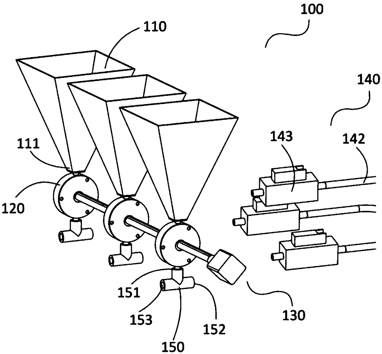
Conveying device applied to 3D printing
A feeding device and 3D printing technology, applied in coating devices, solid material additive processing, processing and manufacturing, etc., can solve the problems of increased manufacturing costs, high price of 3D metal printers, high price and cost, and achieve The effect of improving material performance
- Summary
- Abstract
- Description
- Claims
- Application Information
AI Technical Summary
Benefits of technology
Problems solved by technology
Method used
Image

Examples
Embodiment Construction
[0028] The objects and functions of the present invention and methods for achieving the objects and functions will be clarified by referring to the exemplary embodiments. However, the present invention is not limited to the exemplary embodiments disclosed below; it can be implemented in various forms. The essence of the description is only to help those skilled in the relevant art comprehensively understand the specific details of the present invention.
[0029] Hereinafter, embodiments of the present invention will be described with reference to the accompanying drawings. In the drawings, the same reference numerals represent the same or similar components, or the same or similar steps.
[0030] The 3D metal printers in the prior art all have the following problems: the printing consumables are of the same type, which cannot be switched during the printing process, and the doping ratio of different metal powder consumables cannot be continuously adjusted during the non-stop pri
PUM
 Abstract
Description
Claims
Application Information
 - R&D Engineer
- R&D Manager
- IP Professional
- Industry Leading Data Capabilities
- Powerful AI technology
- Patent DNA Extraction
Browse by: Latest US Patents, China's latest patents, Technical Efficacy Thesaurus, Application Domain, Technology Topic.
© 2024 PatSnap. All rights reserved.Legal|Privacy policy|Modern Slavery Act Transparency Statement|Sitemap