Physiotherapeutic vehicle seat-back cushion
A back cushion and seat cushion technology, applied in the field of car cushions, can solve the problems of poor ventilation and dust collection of car seat cushions, and achieve the effect of re-collecting dust
- Summary
- Abstract
- Description
- Claims
- Application Information
AI Technical Summary
Benefits of technology
Problems solved by technology
Method used
Image


Examples
Embodiment 1
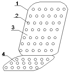
[0026] A physiotherapeutic vehicle seat back cushion, comprising a body 1, the body 1 is integrally formed by a back cushion 3 and a seat cushion 4, connecting lines are evenly arranged in the body 1, and the connecting lines are connected to a terahertz wave generator, and the terahertz wave generator is arranged on The back wall of the back cushion 3 is powered by a battery, the back cushion 3 and the seat cushion 4 are uniformly provided with through holes 2, the through holes 2 are vertically and vertically intersected on the side walls of the back cushion 3 and the seat cushion 4, and are also provided with the back cushion 3 and the seat cushion 4. The through hole 2 in the thickness direction of the seat cushion 4, the back cushion 3 is provided with a spacer, and the spacer and the front side wall of the back cushion 3 form a first collection tank 5;
[0027] A spacer is arranged inside the seat cushion 4, and a second collecting tank 13 is formed between the spacer and th
Embodiment 2
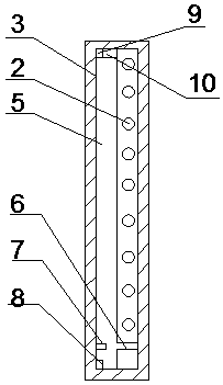
[0030] On the basis of Embodiment 1, a first sieve 10 is provided on the side wall of the first collecting tank 5, and the first sieve 10 is connected to the first driving rod 9, and the first driving rod 9 extends through the slot on the wall of the first collecting tank 5 , the first slag discharge port 8 is set on the lower side of the first collection tank 5;
[0031] The side wall of the second collecting tank 13 is provided with a second sieve 15, the second sieve 15 is connected with the second driving rod 14, and the second driving rod 14 extends through the draw-in groove of the second collecting tank 13 wall, and the second collecting tank 13 side Set the second slag outlet 11;
[0032] The first slag discharge port 8 and the second slag discharge port 11 are provided with jamming; dust may stay on the wall in the first collection tank 5, then the first sieve 10 is driven by the first driving rod 9 to the first collection tank 5 walls. Clean the dust on the surface, an
Embodiment 3
[0034] On the basis of the embodiment 1-2, the lower part of the first collecting tank 5 is provided with a bump 7, and the side wall connecting the through hole 2 and the first collecting tank 5 is provided with a groove 6, and the size of the groove 6 is the same as that of the bump 7 Matching; when in contact with the body 1, the first collection tank 5 collects a certain amount of dust, and the degree of contact with the body 1 deepens at any time, then the bump 7 enters the groove 6, reducing the dust in the first collection tank 5 The through hole 2, too much dust in the through hole 2 affects the effect of the breathable body 1.
PUM
 Abstract
Description
Claims
Application Information
 - R&D Engineer
- R&D Manager
- IP Professional
- Industry Leading Data Capabilities
- Powerful AI technology
- Patent DNA Extraction
Browse by: Latest US Patents, China's latest patents, Technical Efficacy Thesaurus, Application Domain, Technology Topic.
© 2024 PatSnap. All rights reserved.Legal|Privacy policy|Modern Slavery Act Transparency Statement|Sitemap