Phase-controlled antenna element

A phased antenna and component technology, applied in antenna parts, antennas, electrical components, etc., can solve the problems of characteristic dependence and environmental impact, and achieve the effect of less loss and high antenna efficiency

Active Publication Date: 2019-03-01
LISA DRAXLMAIER GMBH
View PDF12 Cites 0 Cited by
  • Summary
  • Abstract
  • Description
  • Claims
  • Application Information

AI Technical Summary

Benefits of technology

The technical effect described in this patented technology allows for accurate adjustment and control over signals being transferred through different types of materials (such as metal) without losing their original properties. This results in improved performance compared to traditional methods like amplification systems where there can lose some important features during transmission.

Problems solved by technology

Technological Problem: Current ControlledPhasing Antenna Arrays require constant adjustment of their phase based on external factors like ambient conditions, including temperature and humidity variations. These limitations limit usability due to increased complexity and cost associated with current methods involving complex electronic circuits.

Method used


Image

  • Phase-controlled antenna element
  • Phase-controlled antenna element
  • Phase-controlled antenna element

Examples


Embodiment Construction

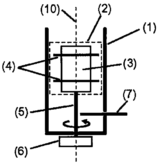
[0085] Figure 4 One embodiment of a phased antenna element is schematically shown.

[0086] The waveguide radiator 1 is designed as a cylindrical horn radiator, and the signal decoupling and coupling-in 7 are implemented in microstrip technology on an HF substrate 71 .

[0087] The microstrip lines 7 for outcoupling and incoupling the circular mode are here designed as rings. This has the advantage that cylindrically symmetrical waveguide modes in the waveguide radiator 1 can be excited and switched off directly and virtually without losses.

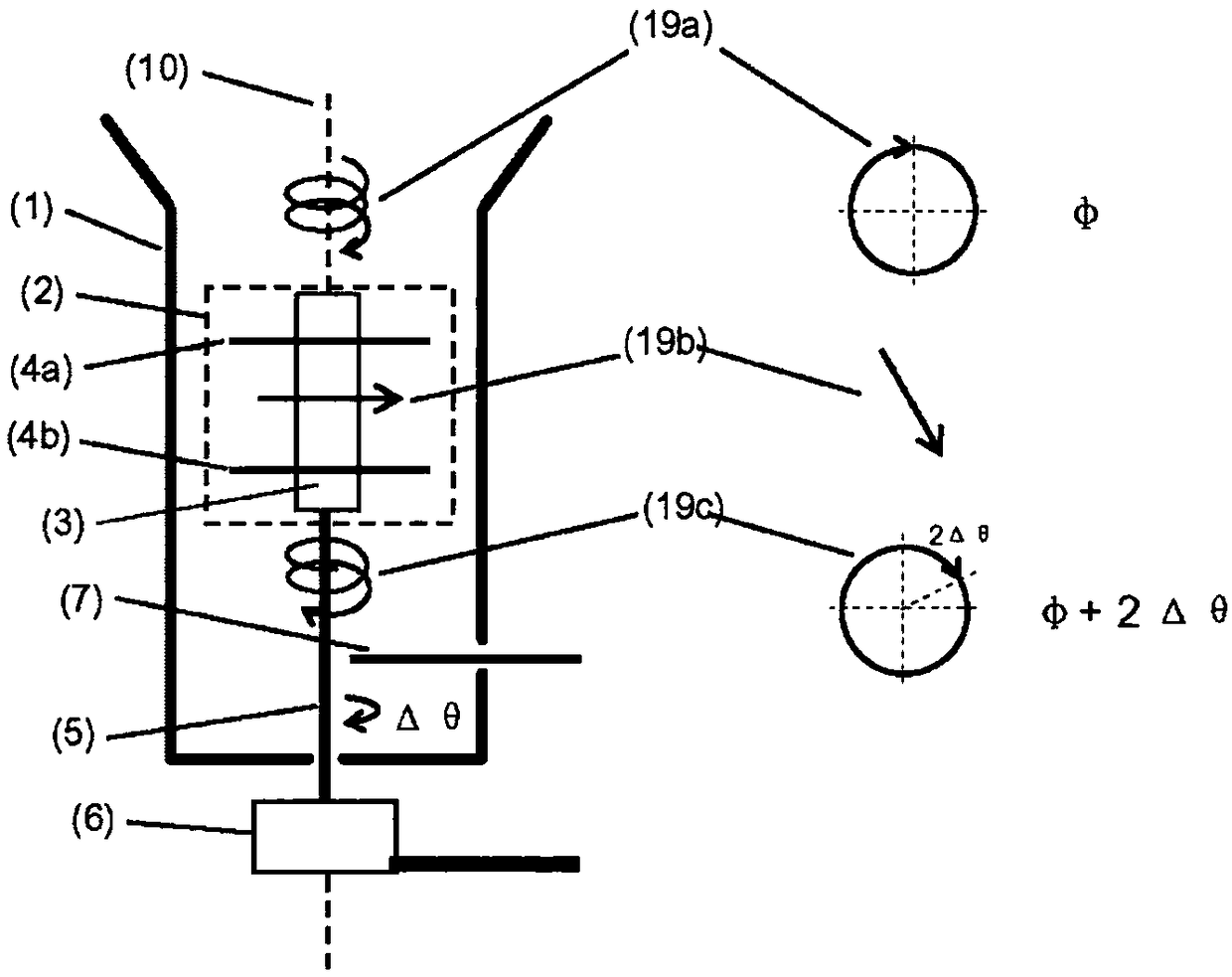
[0088] The waveguide radiator 1 is at least partially cut away at the location of the outcoupling 7 in such a way that the signal outcoupling and incoupling 7 and its substrate 71 are introduced into the waveguide radiator 1 and aligned.

[0089] In order not to interfere with the HF current flowing on the inner wall of the waveguide radiator 1, conductive paths ("vias") 72 are provided, which make it possible to A continuous electrical


PUM


Abstract

The phase-controlled antenna element consists of a waveguide emitter (1) with signal output and signal injection (7), into which a rotatable phase control element (2) is introduced, and a drive unit (6). The phase control element comprises in this case a holder (3), at least two polarisers (4) which are fastened to the holder (3), and a connecting element (5). Each of the at least two polarisers (4) can convert a circularly polarized signal into a linearly polarized signal. The phase control element (2) is rotatably fitted in the waveguide emitter (1) and is connected to the drive unit (6) with the aid of the connecting element (5) in such a manner that the drive unit (6) can rotate the phase control element (2) about the axis (8) of the waveguide emitter (1), as illustrated in the form ofa sketch in fig. 1.

Description


Claims


Application Information

Patent Timeline
Owner LISA DRAXLMAIER GMBH
Why Eureka
Try Eureka