An inductive energy storage type active power filter based on motor winding leakage inductance and a method
A technology of motor windings and source filters, applied in the direction of electrical components, output power conversion devices, etc., can solve the problems of low integration, achieve high integration, reduce secondary ripple components, and improve service life
- Summary
- Abstract
- Description
- Claims
- Application Information
AI Technical Summary
Problems solved by technology
Method used
Image

Examples
Embodiment 1
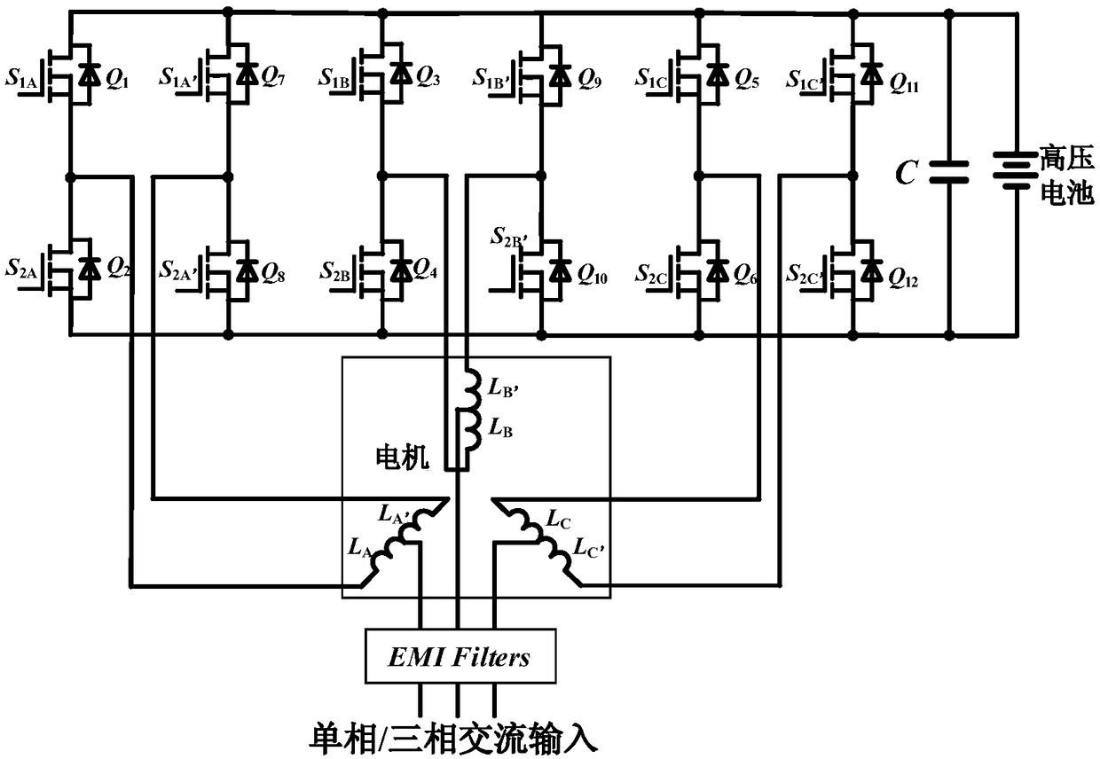
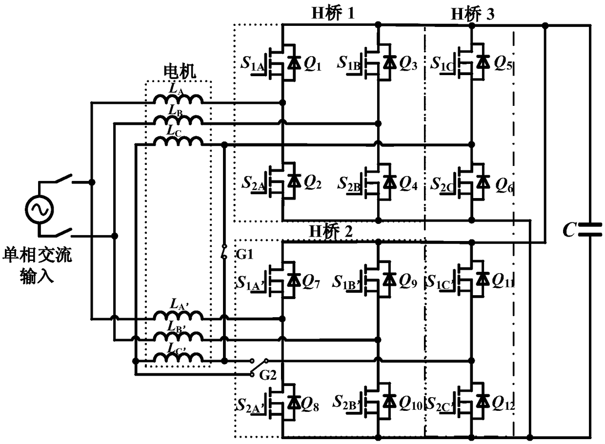
[0061] An inductive energy storage active filter based on the leakage inductance of motor windings, see figure 1 and figure 2 , the active filter consists of:
[0062] The embodiment of the present invention is based on the electric vehicle integrated charging system, based on figure 1 An inductive energy storage active filter based on the leakage inductance of the motor winding is proposed to suppress the secondary ripple voltage of the DC side bus.
[0063] Depend on figure 2 It can be seen that the topology of the entire active filter is mainly composed of three H-bridges with a common DC bus (ie, H-bridge 1, H-bridge 2, and H-bridge 3) and a three-phase double-layer winding motor with a center tap. And the topology works in single-phase charging mode. Two of the H-bridges (H-bridge 1 and H-bridge 2) are connected in parallel at the input and output in parallel, and the L in the three-phase double-layer motor winding A , L A’ and L B , L B’ The leakage inductance is
Embodiment 2
[0070] An embodiment of the present invention provides an inductive energy storage type active filter control method based on the leakage inductance of motor windings, the method comprising the following steps:
[0071] 101: Analyze the topology structure with secondary ripple suppression function in the integrated charging system;
[0072] Wherein, the step 101 is specifically: adding a group of relays (two) to switch the working mode of the charging system: traction mode and charging mode.
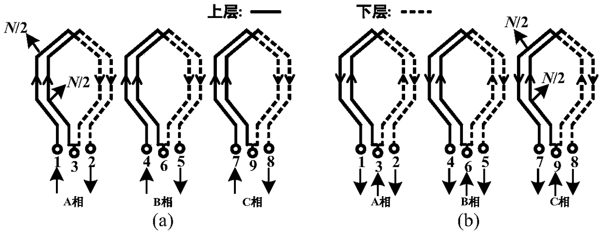
[0073] The structure and connection mode of the stator winding of the three-phase asynchronous motor are given, and the current flow path and the generated magnetomotive force of the adopted winding with center tap working in different modes are analyzed, so as to obtain the windings of each phase in the charging mode The self-inductance is zero (the magnetomotive forces cancel each other out), but the leakage inductance still exists.
[0074] 102: Use a DC converter with bidirectional ene
Embodiment 3
[0080] Combine below Figure 5-Figure 8 , and the specific calculation formula further introduces the scheme in embodiment 2, see the following description for details:
[0081] 1. The current setting when the inductor current flows in the form of DC
[0082] Depend on Figure 5 and Figure 6 (a) It is known that when the inductor current flows in the form of direct current, the converter has four operating modes in one cycle.
[0083] Modal 1: When S 1C S 2C S 1C’ S 2C’ =1001, the switching tube Q 5 and Q 12 conduction, the switching tube Q 6 and Q 11 off. At this time, the inductance passes through the power switch tube Q 5 and Q 12 Energy storage is carried out, and the inductor current increases positively, and the voltage at both ends of the inductor is the DC bus voltage.
[0084] Mode 2: When S 1C S 2C S 1C’ S 2C’ =0000, the switching tube Q 5 , Q 6 , Q 11 and Q 12 Both are turned off, because the direction of the inductor current cannot change abrupt
PUM
 Abstract
Description
Claims
Application Information
 - R&D Engineer
- R&D Manager
- IP Professional
- Industry Leading Data Capabilities
- Powerful AI technology
- Patent DNA Extraction
Browse by: Latest US Patents, China's latest patents, Technical Efficacy Thesaurus, Application Domain, Technology Topic.
© 2024 PatSnap. All rights reserved.Legal|Privacy policy|Modern Slavery Act Transparency Statement|Sitemap