Integrated system and control method for achieving heat exchange and power generation through liquid nitrogen

An integrated system, electromagnetic control valve technology, applied in heat exchanger types, indirect heat exchangers, machines/engines, etc., can solve problems such as the inability to dissipate the heat of the internal combustion engine cylinder normally, the increased heat load of components, and the hidden danger of internal combustion engine safety. , to achieve the effect of obvious cooling effect, short cooling time and low cost

Pending Publication Date: 2019-04-05
TIANJIN UNIV
View PDF0 Cites 2 Cited by
  • Summary
  • Abstract
  • Description
  • Claims
  • Application Information

AI Technical Summary

Problems solved by technology

When the internal combustion engine runs under heavy load conditions for a long time, phenomena such as boiling of the coolant may occur, the heat in the cylinder of the internal combust

Method used


Image

  • Integrated system and control method for achieving heat exchange and power generation through liquid nitrogen

Examples


Example Embodiment

[0020] The present invention will be described in detail below in conjunction with the accompanying drawings and specific implementation.

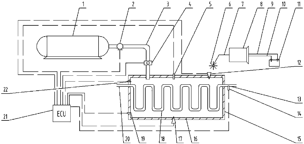
[0021] As shown in the accompanying drawings, a heat exchange-power generation integrated system using liquid nitrogen of the present invention includes an electronic control unit ECU21, and the outlet of the high-pressure nitrogen storage tank 1 is sequentially connected to the liquid nitrogen pump 2 and the first through the liquid nitrogen pipeline 3. The electromagnetic control valve 4 and the outlet of the liquid nitrogen pipeline 3 are inserted into the liquid nitrogen inlet on the top of the heat exchange box 15 to set.

[0022] A heat exchange pipeline 18 for transporting heat exchange fluid is installed in the heat exchange box 15, and the inlet and outlet of the heat exchange pipeline 18 extend out from the left and right sides of the heat exchange box 15 respectively. The inlet of the heat exchange pipeline is connected to the outl


PUM


Abstract

The invention discloses an integrated system and control method for achieving heat exchange and power generation through liquid nitrogen. According to the system, an electronic control unit (ECU) controls a liquid nitrogen pump and solenoid valves to act to guide refrigerating fluid into a heat exchange box. Heat exchange fluid or gas or liquid in need releases heat to the liquid nitrogen in a heat exchange pipe, so that the cooling purpose is achieved; and meanwhile, power generation is further conducted through heated and expanded nitrogen gas, so that energy recycling is achieved. The solenoid valves are controlled to act through the electronic control unit (ECU), and the temperature of the heat exchange fluid or gas or liquid can be controlled to be at a set value, so that intelligentadjustment of the temperature is achieved. The integrated system is simple in structure, low in cost and convenient to maintain and can be applied to equipment high in thermal load and heat exchange requirement, such as an engine, so that rapid cooling is achieved.

Description


Claims


Application Information

Patent Timeline
Owner TIANJIN UNIV
Why Eureka
Try Eureka