Directional solidification casting mold device

A technology of directional solidification and casting mold, applied in the field of casting equipment, can solve the problems of short cooling time, low cooling efficiency, long cooling time, etc., and achieve the effects of short cooling time, high cooling efficiency and low cost

Pending Publication Date: 2019-05-07
浙江信和科技股份有限公司
View PDF0 Cites 0 Cited by
  • Summary
  • Abstract
  • Description
  • Claims
  • Application Information

AI Technical Summary

Problems solved by technology

[0003] The purpose of the present invention is to provide a short cooling time, high cooling efficiency, simple operation, stable operation and low cost for the shortcomings of the existing casting mold in the c

Method used


Image

  • Directional solidification casting mold device
  • Directional solidification casting mold device

Examples


Example Embodiment

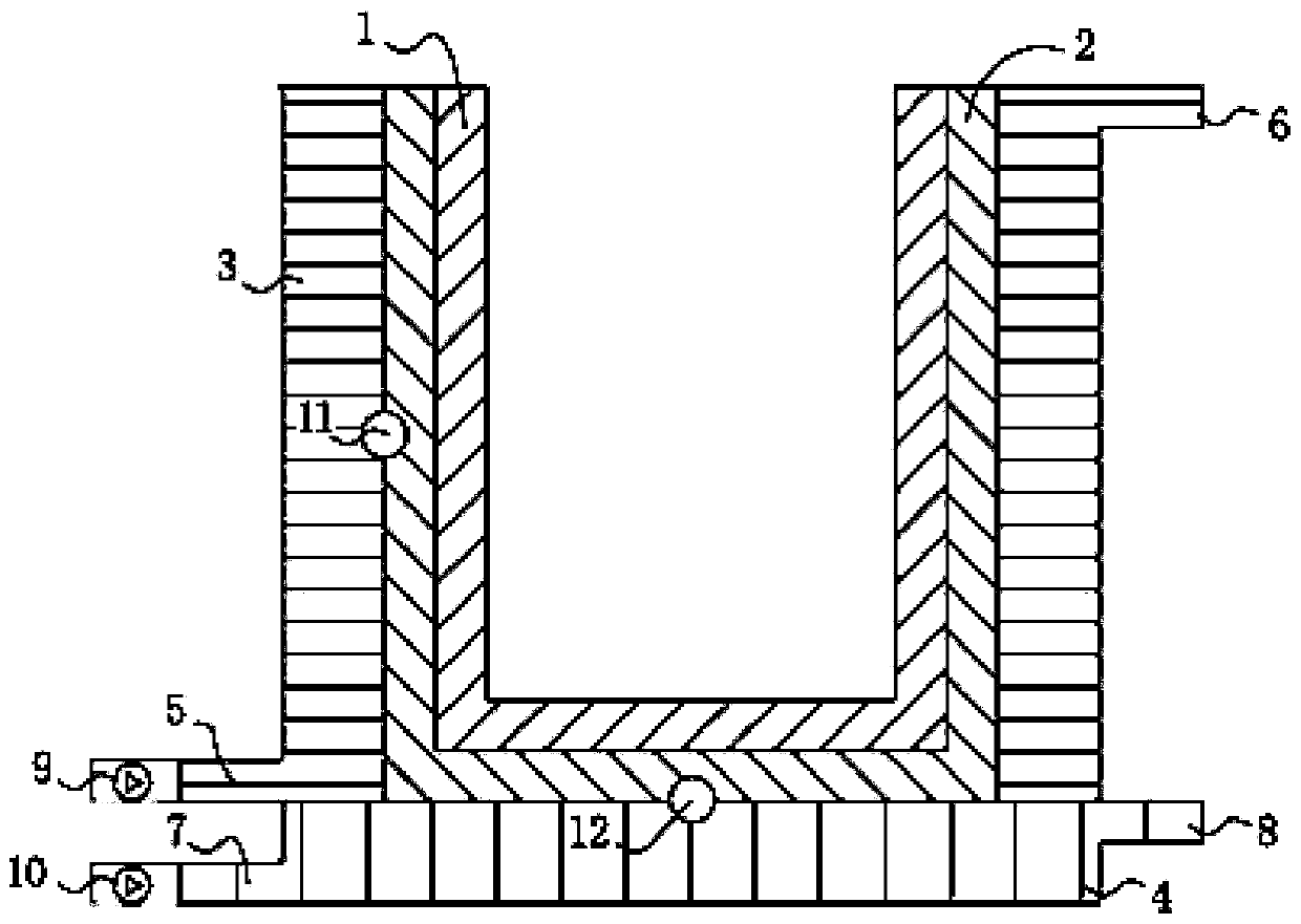
[0016] In the following, the present invention will be further described through embodiments with reference to the drawings.

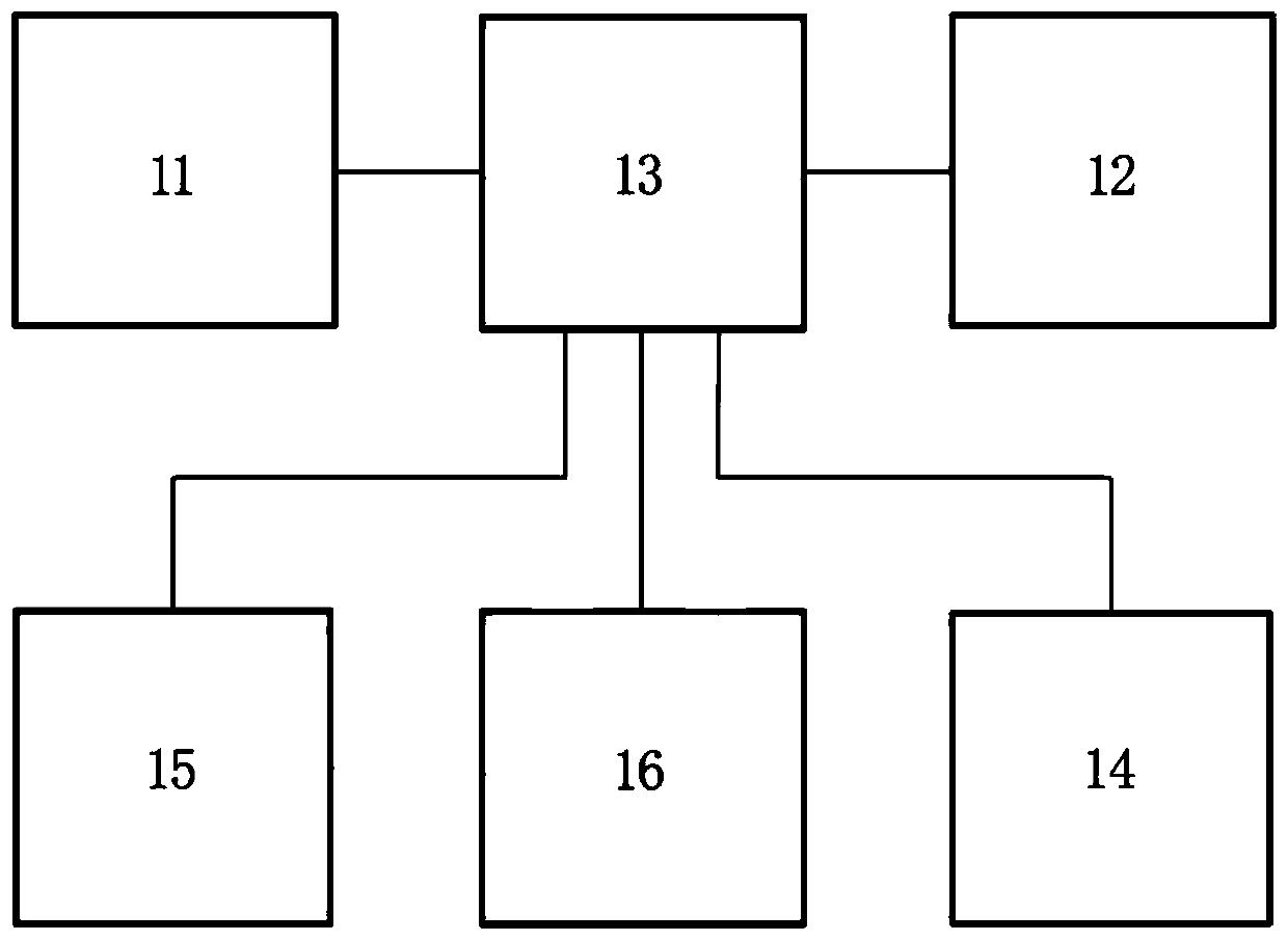
[0017] Reference attached figure 1 And figure 2 , A directional solidification casting mold device, comprising an inner barrel 1, a heat-conducting barrel 2, a radial water cooling device 3 and a bottom water cooling device 4. The inner barrel 1 is set in the heat-conducting barrel 2, and the outer side of the inner barrel 1 and the inner wall of the heat-conducting barrel 2 The outer end surface of the bottom of the inner barrel 1 and the inner surface of the bottom of the heat conducting barrel 2 are tightly attached together; in order to obtain a good surface quality ingot, the inner barrel 1 uses a graphite barrel; To quickly transfer the heat of the ingot to improve the cooling capacity of the device, the heat-conducting barrel 2 is made of a metal material with high thermal conductivity. Preferably, the heat-conducting barrel 2 is a copper barrel, whe


PUM


Abstract

The invention relates to a directional solidification casting mold device. The casting mold device comprises an inner barrel, a heat conduction barrel, a radial water cooling device, a bottom water cooling device and an intelligent temperature control circuit; wherein the inner barrel is arranged in the heat conduction barrel, and the inner barrel and the heat conduction barrel are closely attached together; the radial water cooling device is provided with a radial water cooling device water inlet and a radial water cooling device water outlet, and a first electric valve is arranged at the radial water cooling device water inlet; the bottom water cooling device is provided with a bottom water cooling device inlet and a bottom water cooling device water outlet, and a second electric valve is arranged at the bottom water cooling device water inlet; and the intelligent temperature control circuit comprises a main control board, a heat conduction barrel side wall temperature sensor, a heatconduction barrel bottom temperature sensor, the first electric valve, the second electric valve, and a power circuit. The directional solidification casting mold device has the characteristics of short cooling time, high cooling efficiency, easy operation, small occupied space, and controllability in surface quality and internal structure of ingots during the process of the casting technology.

Description


Claims


Application Information

Patent Timeline
Owner 浙江信和科技股份有限公司
Why Eureka
Try Eureka