Smart door real-time two-way video intercom system

A technology of intercom system and smart door, which is applied in two-way working system, closed-circuit television system, TV, etc., can solve problems such as inconvenience, and achieve the effect of saving trouble

Inactive Publication Date: 2019-04-23
浙江星月安防科技有限公司
View PDF7 Cites 0 Cited by
  • Summary
  • Abstract
  • Description
  • Claims
  • Application Information

AI Technical Summary

Problems solved by technology

[0003] However, the indoor unit is usually installed indoors near the security door, and indoor residents need to move to the door to perform voice and video interaction; especially when the head of the household is in

Method used


Image

  • Smart door real-time two-way video intercom system

Examples


Embodiment Construction

[0034] The present invention will be described in further detail below in conjunction with the accompanying drawings.

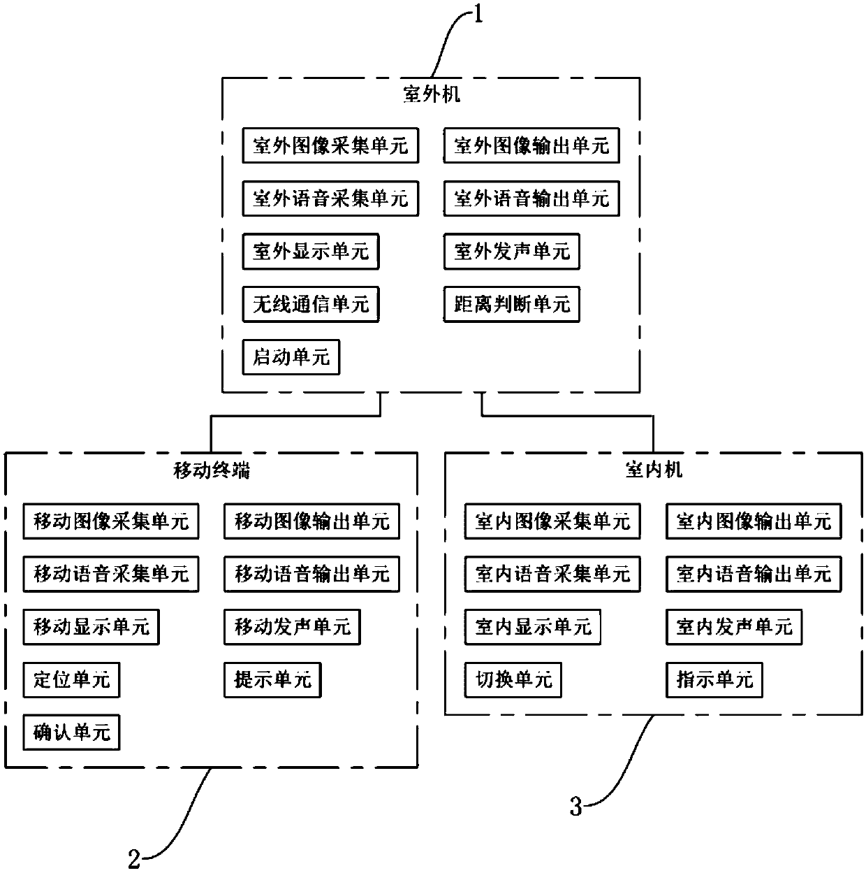
[0035] A real-time two-way visual intercom system for smart doors disclosed in this embodiment, such as figure 1 As shown, it includes an outdoor unit 1 and a mobile terminal 2 . Among them, the outdoor unit 1 is set on the side of the door away from the locked space, and the mobile terminal 2 is preferably a mobile device with wireless communication capabilities such as a smart phone and a tablet computer, and the mobile terminal 2 mentioned in this embodiment is all Refers to mobile devices owned by indoor occupants. The outdoor unit 1 includes an outdoor image acquisition unit, an outdoor image output unit, an outdoor voice acquisition unit, an outdoor voice output unit, an outdoor display unit, an outdoor sounding unit, and a wireless communication unit. More specifically, the outdoor image acquisition unit is preferably a high-definition camera, the outdo


PUM


Abstract

The present invention discloses a smart door real-time two-way video intercom system, which solves a problem that it is inconvenient for a household at home to perform communication when the householdis far away from the doorway. Key points of a technical solution of the present invention includes: an outdoor unit, including an outdoor image collection unit, an outdoor image output unit, an outdoor voice collection unit, an outdoor voice output unit, an outdoor display unit, an outdoor sounding unit, and a wireless communication unit; a mobile terminal, including a moving image collection unit, a moving image output unit, a moving voice collection unit, a moving voice output unit, a moving display unit, and a moving sounding unit. The smart door real-time two-way video intercom system ofthe present invention enables the outdoor unit to directly perform voice and video interaction with the mobile terminal, to get rid of restraints of the indoor unit, so that interaction between the household at home and an outdoor visitor is not limited by a location of the household. Therefore, it is more convenient and an unnecessary trouble is reduced.

Description


Claims


Application Information

Patent Timeline
Owner 浙江星月安防科技有限公司
Why Eureka
Try Eureka