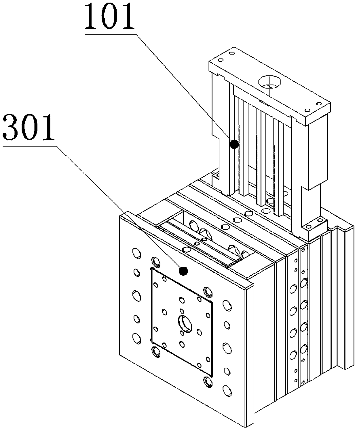
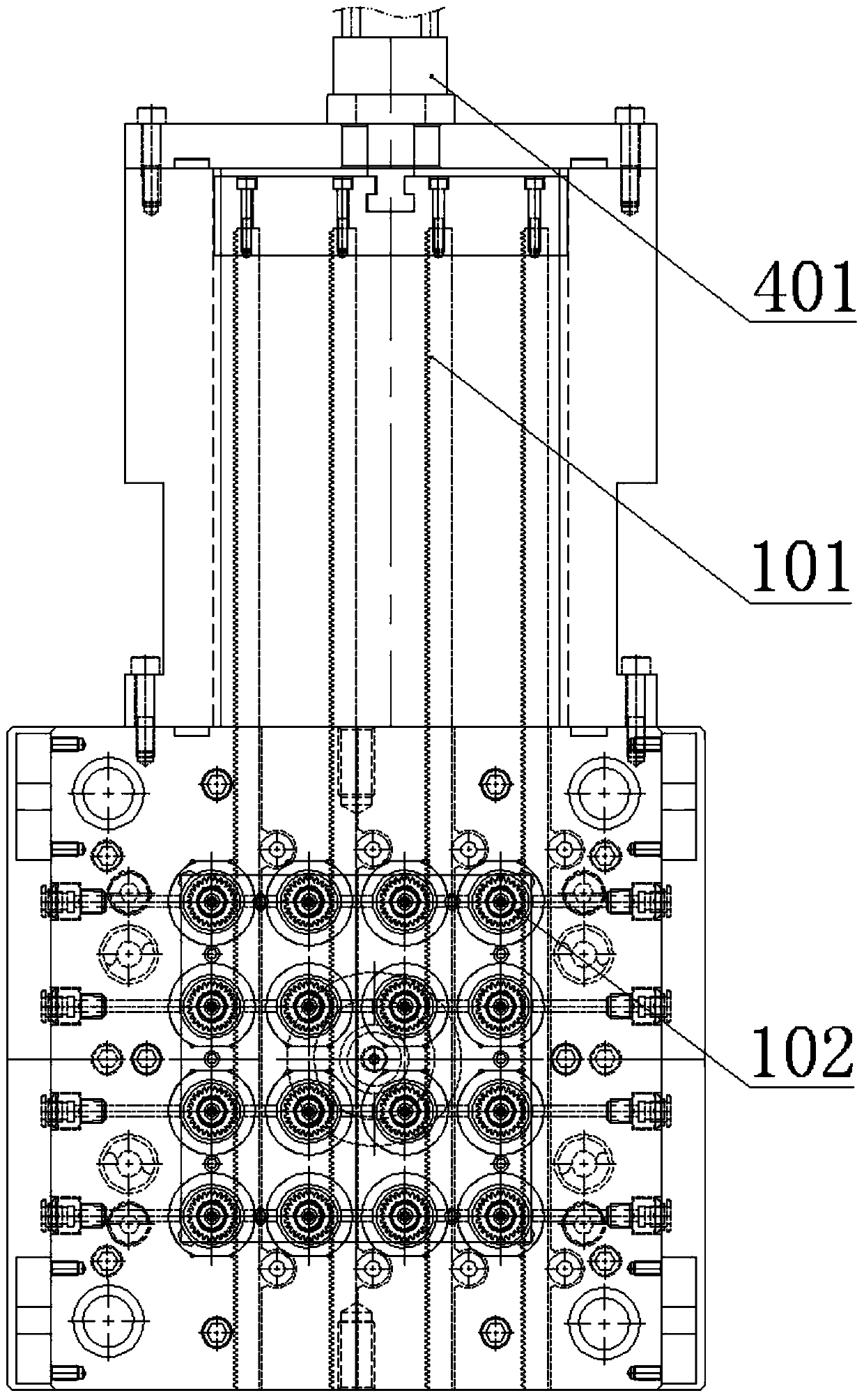
Screw tooth core-returning mechanism and die

A technology of core-removing and twisting teeth, applied in the field of twisting-thread core-extraction mechanism and molds, can solve the problems of crushed copper braces, wear of gears, and multiple movements of inserts, and achieves the effect of reducing gear transmission wear and reducing wear

Pending Publication Date: 2019-05-17
广州莱汇科技有限公司
View PDF0 Cites 2 Cited by
  • Summary
  • Abstract
  • Description
  • Claims
  • Application Information

AI Technical Summary

Problems solved by technology

[0002] In the prior art, the core ejection mechanism of injection molding is driven by multiple gears, the gears will inevitably wear out after a long time of production, and the cumulative gap will become larger and larger if there are more gears, resulting in inconsistent product screw teeth; core ejection There

Method used


Image

  • Screw tooth core-returning mechanism and die
  • Screw tooth core-returning mechanism and die
  • Screw tooth core-returning mechanism and die

Examples


Embodiment Construction

[0035] The technical solutions of the present application will be clearly and completely described below in conjunction with the accompanying drawings. Apparently, the described embodiments are some of the embodiments of the present application, not all of them. Based on the embodiments in this application, all other embodiments obtained by persons of ordinary skill in the art without making creative efforts belong to the scope of protection of this application.

[0036] In the description of this application, it should be noted that the terms "center", "upper", "lower", "left", "right", "vertical", "horizontal", "inner", "outer" etc. The indicated orientation or positional relationship is based on the orientation or positional relationship shown in the drawings, and is only for the convenience of describing the present application and simplifying the description, rather than indicating or implying that the referred device or element must have a specific orientation, use a specifi


PUM


Abstract

The invention relates to the technical field of injection moulding, in particular to a screw tooth core-returning mechanism and a die. The screw tooth core-returning mechanism comprises a rack, a gear, a center shaft, a guide shaft, a first insert and a first insert pin, wherein the center shaft is of hollow structure; the gear is coaxially arranged on the center shaft and is meshed with the rack;a thread is formed in one end of a gear shaft; the center shaft is coaxially connected with the guide sleeve; the first insert is arranged in the center shaft; an exhausting passage is arranged on the first insert; the first insert pin is arranged in the first insert; and an exhausting groove is formed in the axial direction of the first insert pin and communicates with the exhausting passage. The die comprises a die box and a plurality of screw tooth core-returning mechanisms; the screw tooth core-returning mechanisms are mounted on the die box. The rack is directly meshed with the gear to reduce driving abrasion of the gear; the center shaft is coaxially connected with the guide sleeve, so that guiding exit of the center shaft is facilitated, and abrasion of the center shaft is reduced;and the exhausting groove communicates with the exhausting passage to exhaust air in the die to facilitate forming of colloid in a cavity.

Description


Claims


Application Information

Patent Timeline
Owner 广州莱汇科技有限公司
Why Eureka
Try Eureka