Hyperboloidal sewage stirrer

A hyperboloid and agitator technology, which is applied in water/sewage treatment, water/sludge/sewage treatment, mixers with rotating agitation devices, etc., can solve the problem that the mixing effect is not particularly ideal, and low speed and high efficiency cannot be achieved. , high cost of the aerator, etc., to achieve the effect of increasing the stirring effect, improving the pushing flow ability, and reducing energy consumption

Pending Publication Date: 2019-05-28
尚川(北京)水务有限公司
View PDF0 Cites 4 Cited by
  • Summary
  • Abstract
  • Description
  • Claims
  • Application Information

AI Technical Summary

Problems solved by technology

[0002] The mixing unit is an important sewage treatment device, which is suitable for urban and rural sewage treatment plants. The quality of its installation and use has a great impact on the operation of sewage treatment. Most of the existing biochemical pools use paddle mixers, namely One impeller is installed on one submersible motor, the number of blades is generally three, the stirring effect is not par

Method used


Image

  • Hyperboloidal sewage stirrer
  • Hyperboloidal sewage stirrer

Examples


Embodiment 1

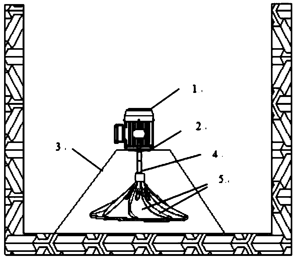
[0027] Such as figure 1 As shown, this embodiment provides a hyperboloid sewage agitator, including a support structure, a driving device and a stirring part 5; the supporting structure is arranged in the sewage tank, the driving device is arranged on the top of the supporting structure, and the driving device is used to drive the stirring part 5 .

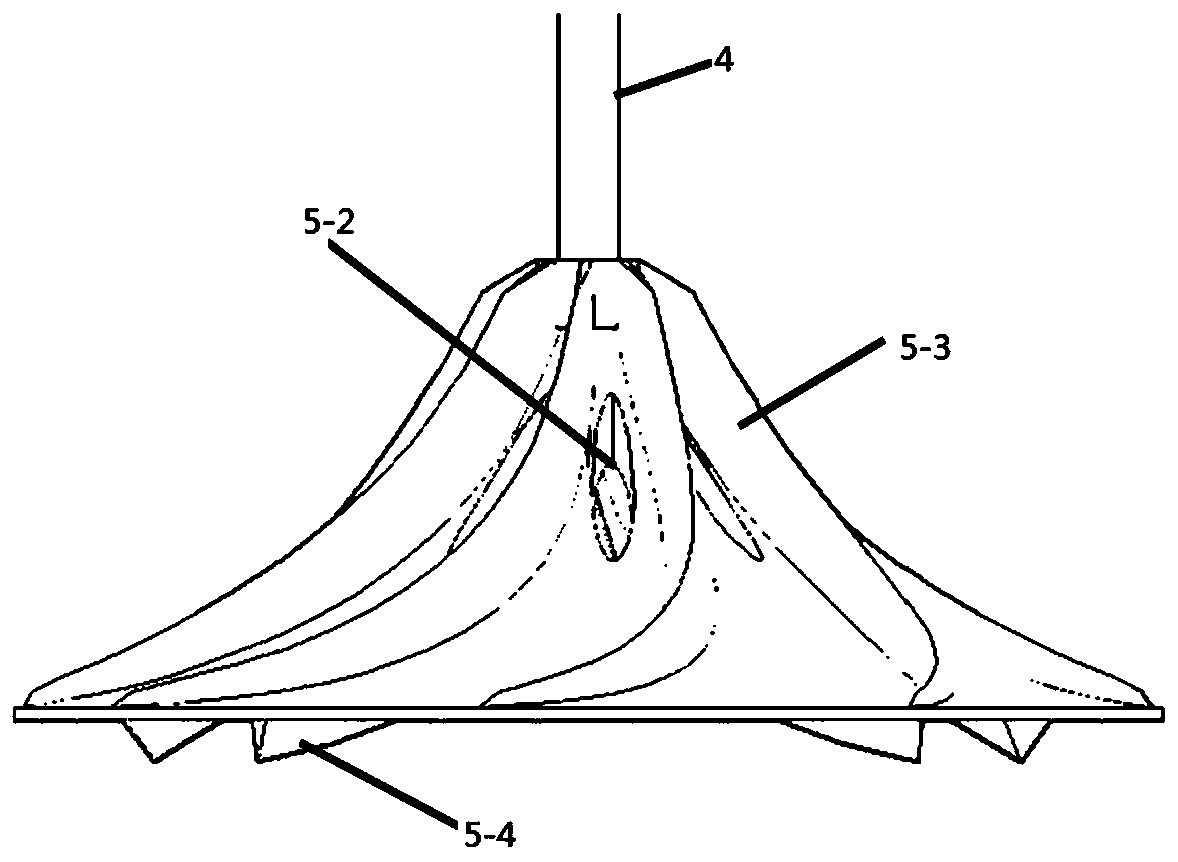
[0028] In this specific embodiment, the supporting structure includes a supporting frame 3 , and the driving device is arranged on the top of the supporting frame 3 . The driving device is the motor 1. The stirring part 5 is arranged on the power output shaft of the motor 1 . The stirring part 5 includes a hub and eight guide paddles 5-3; the eight guide paddles 5-3 are uniformly arranged on the upper surface of the hub. The hub is a flared structure with the smaller end of the hub at the top. The upper part of the hub is provided with eight discharge ports 5-2. The discharge port 5-2 is located between adjacent guide paddles 5-


PUM


Abstract

The invention discloses a hyperboloidal sewage filter, and relates to the technical field of sewage treatment equipment. The main structure of the hyperboloidal sewage filter comprises a supporting structure, a driving device and a stirring part. The flow propelling ability of the stirring part is increased to the maximum due to the structure of a flow guiding paddle, the width of the flow guidingpaddle is gradually enlarged from the bottom end to the top end, the axial flow propelling ability of the stirring part is greatly increased, stirring can be more uniform, the power consumption can be reduced, and the stirring effect is greatly increased; shearing ribs are capable of shearing air bubbles of an aerator, the diameter of the air bubbles can be smaller, and the oxygen utilization rate is higher, so that the energy consumption of the aerator can be reduced, and the aeration effect can be enhanced.

Description


Claims


Application Information

Patent Timeline
Owner 尚川(北京)水务有限公司
Why Eureka
Try Eureka