Beam column decoration assembly in public place

A public place, beam-column technology, applied in covering/lining, building, building structure, etc., can solve the problem of inability to change the decoration structure, achieve the effect of improving the decoration effect and reducing the safety hazard

Active Publication Date: 2019-06-07
深圳市博大建设集团有限公司
View PDF6 Cites 0 Cited by
  • Summary
  • Abstract
  • Description
  • Claims
  • Application Information

AI Technical Summary

Problems solved by technology

However, regardless of the above methods, it is generally impossible to change

Method used


Image

  • Beam column decoration assembly in public place
  • Beam column decoration assembly in public place
  • Beam column decoration assembly in public place

Examples


Embodiment 1

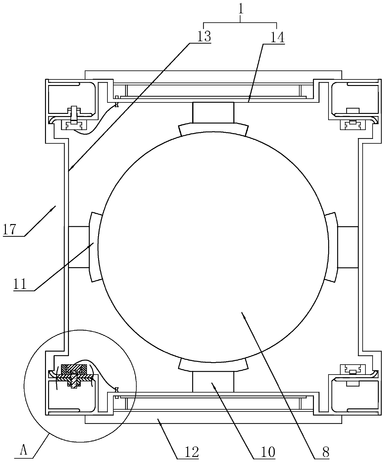
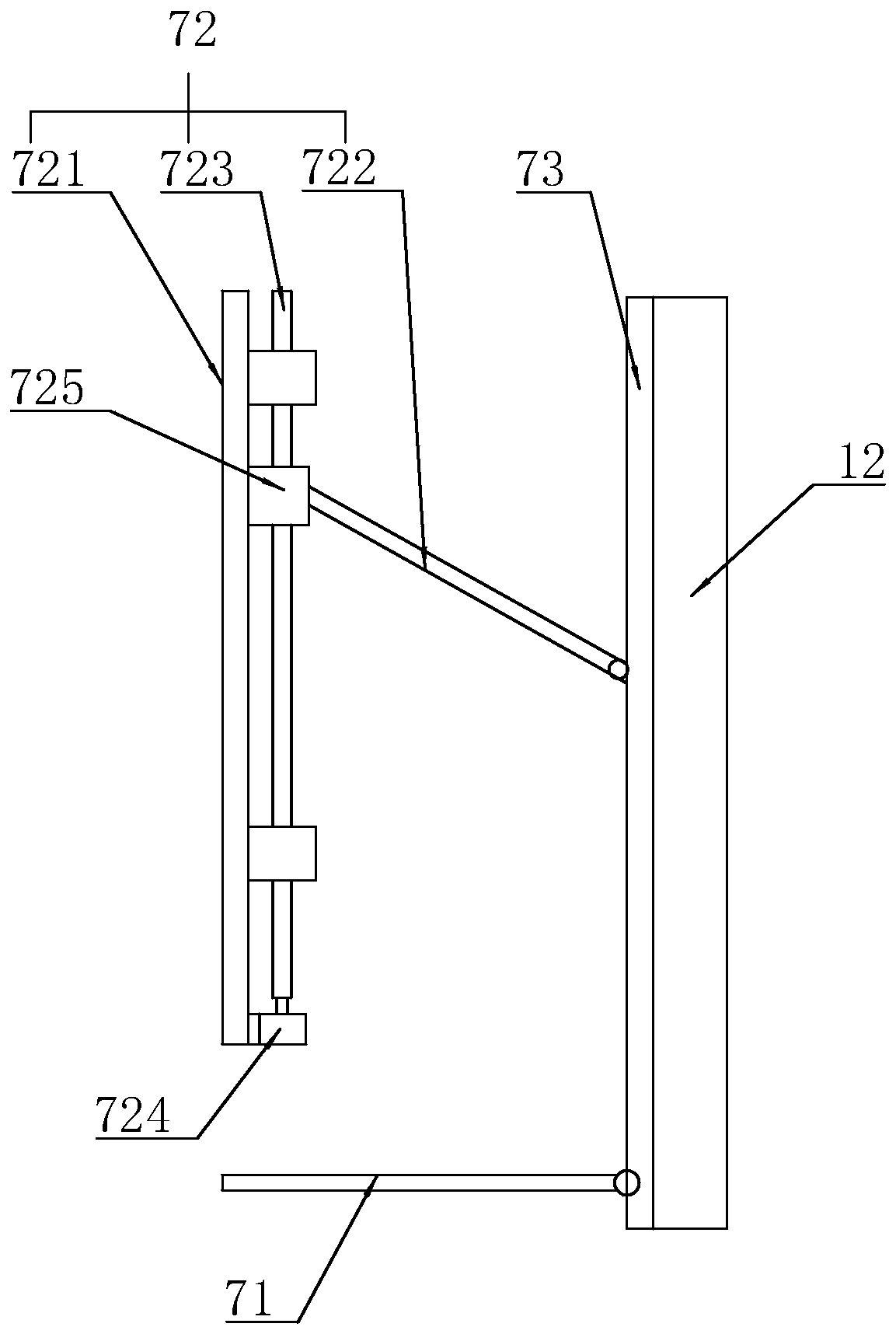
[0036] Embodiment 1: A beam and column decoration assembly in public places, such as figure 1 and figure 2 As shown, it includes a base frame unit 1 and a display screen 12 fixed to the outside of the base frame unit 1 , and the outer surface of the base frame unit 1 is recessed inwardly to form a mounting groove 17 for the display screen 12 to engage. Mounting groove 17 is provided with upper frame 72, lower frame 71 and mounting frame 73. Fixed connection. The upper frame 72 includes an inner frame 721 fixed on the inner wall of the mounting groove 17, an outer rod 722 hinged at one end of the mounting frame 73, a screw rod 723 that is rotatably connected to the inner frame 721, a drive motor 724 that drives the screw rod 723 to rotate, and a screw threaded with the screw rod 723. The adapter 725 , the other end of the outer rod 722 is hinged to the adapter 725 , and the inner side of the adapter is slidably connected to the inner frame 721 .

[0037] refer to figure 1 and


PUM


Abstract

The invention relates to a beam column decoration assembly in a public place. The beam column decoration assembly comprises a base frame unit and a display screen fixed to the outer side of the base frame unit, the base frame unit comprises a first frame body and a second frame body which are mutually buckled in a mode of surrounding a beam column, cambered surface supports which abut against thesurface of the beam column are arranged on the inner sides of the first frame body and the second frame body correspondingly, a second buckling unit with opening grooves facing the two sides is arranged at the end of the second frame body, and the first frame body is provided with a first buckling unit, wherein the first buckling unit and the second buckling unit are fixed in an buckled mode, andthe first buckling unit is used for sealing the opening grooves; and the surfaces of the outer sides of the first frame body and the second frame body are sunken towards the inner sides to form mounting grooves for allowing the display screen to be embedded. The beam column decoration assembly has the advantages that the surface of the outer side of the beam column is changed to be of a structurewith a decoration outer layer capable of being mounted, the cambered surface can be changed into the plane so as to adapt to mounting of the display screen, and the decoration effect is freely changedaccording to the need.

Description


Claims


Application Information

Patent Timeline
Owner 深圳市博大建设集团有限公司
Why Eureka
Try Eureka