A depth map reconstruction method combining laser points and mean shift

A mean shift algorithm and mean shift technology, applied in the field of image processing, can solve the problems of noise and holes in the model, and achieve the effect of reducing a large number of iterations, complete features, and strong robustness

Pending Publication Date: 2019-06-28
HARBIN UNIV OF SCI & TECH
View PDF9 Cites 1 Cited by
  • Summary
  • Abstract
  • Description
  • Claims
  • Application Information

AI Technical Summary

Benefits of technology

By combining two or more lasers together at specific locations on an object's surface, it becomes easier for experts to interpret how objects look like due to their shiny surfaces that appear brighter than other parts when viewed from above them through windows. These techniques help reduce errors during image processing by reducing overall these issues associated with conventional means such as average-shift algorithm.

Problems solved by technology

This patented technology describes how depth camera systems use advanced techniques such as stereoscopic imaging or structural analysis to create accurate three dimensional models from images captured with specialized equipment like depth sensors. However, these processes often result in errors due to hole/noise issues during the process. These technical problem addressed by this patents include finding better ways to reduce unwanted background signals while maintain good quality depth maps without introducing any new sources of noises (such as laser points).

Method used


Image

  • A depth map reconstruction method combining laser points and mean shift
  • A depth map reconstruction method combining laser points and mean shift
  • A depth map reconstruction method combining laser points and mean shift

Examples


Embodiment Construction

[0038] The specific implementation manners of the present invention will be further described in detail below in conjunction with the accompanying drawings.

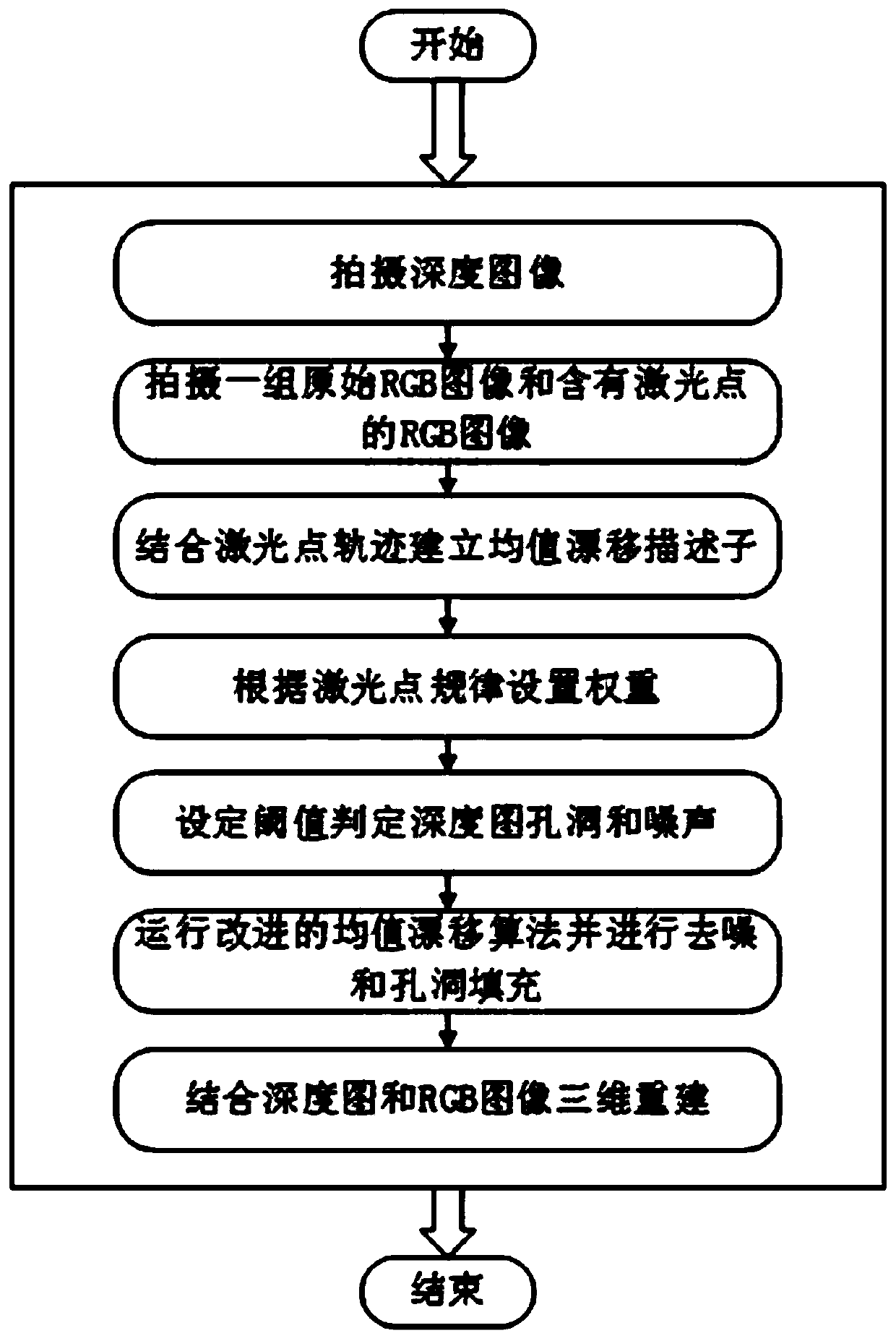
[0039] The present invention provides a depth map reconstruction method combined with laser point and mean shift, the flow chart is as follows figure 1 As shown, the method includes the following steps:

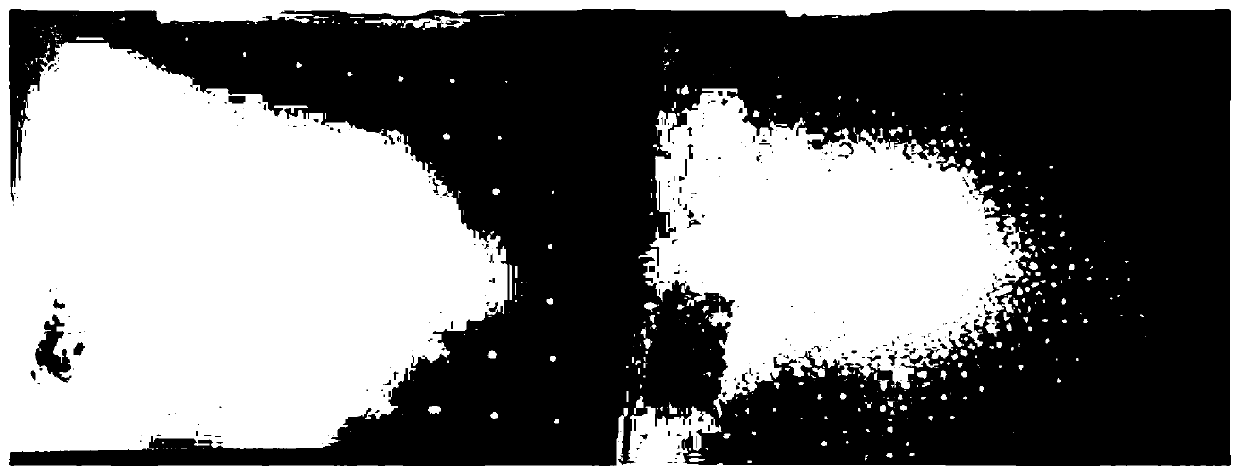
[0040] (1) Take a depth image;

[0041] (2) Take a group of original RGB images and RGB images containing laser points;

[0042] (3) Establish a mean shift descriptor in combination with laser point trajectories;

[0043] (4) Set the weight according to the laser point rule;

[0044] (5) Set the threshold to determine holes and noise in the depth map;

[0045] (6) Run the improved mean shift algorithm and perform denoising and hole filling;

[0046] (7) Combining depth map and RGB image for reconstruction.

[0047] like figure 2 As shown, on the basis of the above solution, further, in step (2), a laser point is pr


PUM


Abstract

The invention provides a depth map reconstruction method combining laser points and mean shift. The depth map reconstruction method comprises the following implementation steps: (1) shooting a depth image; (2) shooting an RGB image containing laser points; (3) establishing a mean shift descriptor by combining a laser point track; (4) setting a weight according to a laser point rule; (5) setting athreshold value to judge holes and noise of the depth map; (6) de-noising the depth map and filling holes; And (7) reconstructing by combining the depth map and the RGB image. According to the method,a large number of object characteristics are reserved, high robustness is achieved, and a good reconstruction effect can be kept in various environments and on a shot object.

Description


Claims


Application Information

Patent Timeline
Owner HARBIN UNIV OF SCI & TECH
Why Eureka
Try Eureka