Glove massager

A massager and glove technology, applied in pneumatic massage, massage auxiliary products, physical therapy and other directions, can solve the problems of less attention to finger massage functions, insufficient massage functions, and unsatisfactory massage effects, and achieve rich massage functions. , the effect of promoting blood circulation

Pending Publication Date: 2019-08-16
XIAMEN COMFORT SCIENCE & TECHNOLOGY GROUP CO LTD +1
View PDF0 Cites 2 Cited by
  • Summary
  • Abstract
  • Description
  • Claims
  • Application Information

AI Technical Summary

Benefits of technology

The technical effect of this innovator lies within its design that allows for direct pressure by pressing two hands together without having them stretch out or tighten up again after being used repeatedly over time. This improves the quality of these product's benefits such as improved blood flow and more effective treatment options.

Problems solved by technology

Technics: Current methods used to treat painful conditions involve physical therapies or medications but they cannot provide complete relief over these symptoms without restrictive restrictions during use.

Method used


Image

  • Glove massager
  • Glove massager
  • Glove massager

Examples


Embodiment Construction

[0027] The present invention will be described in further detail below in conjunction with the accompanying drawings and specific embodiments, but not as a limitation of the present invention.

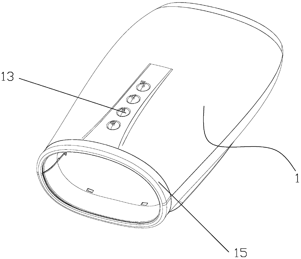
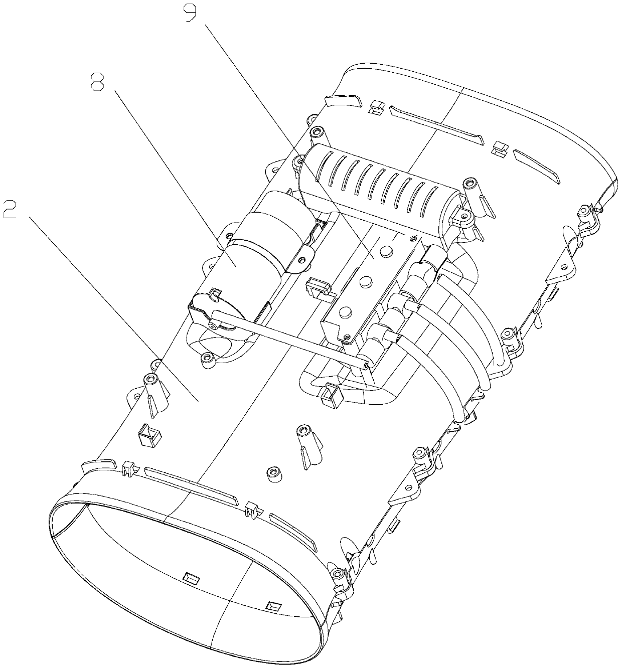
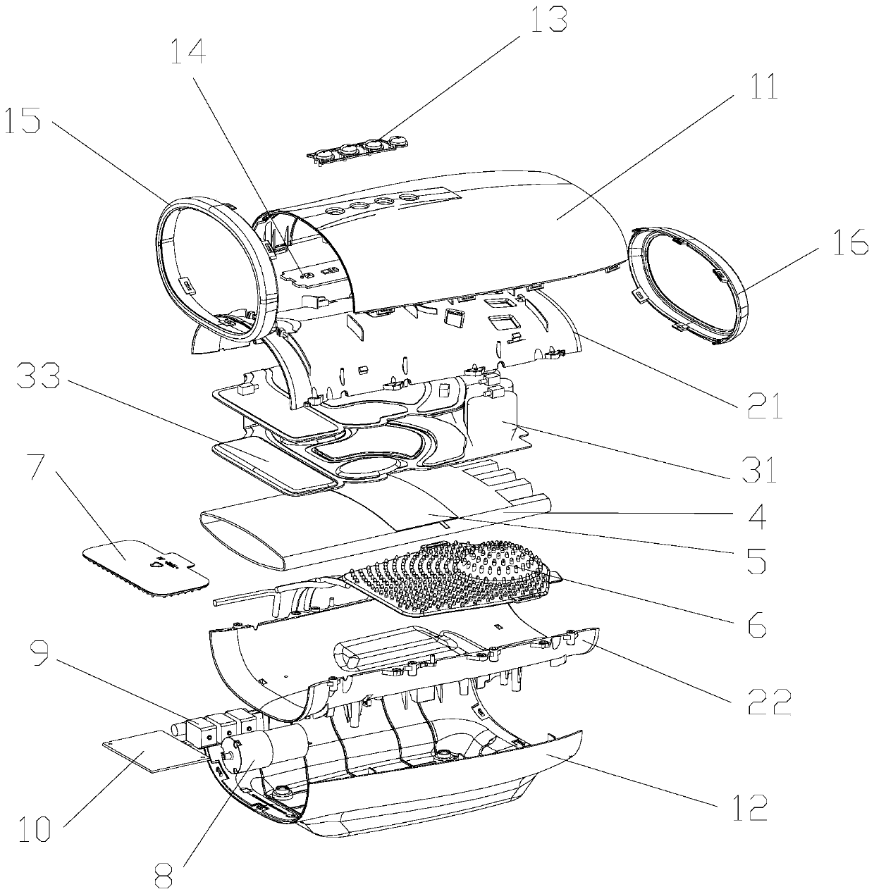
[0028] See Figure 1 to Figure 5 As shown, the embodiment of the present invention provides a glove massager, including an air bag assembly 3 , an air pump 8 , an air valve, a circuit board 10 and a housing 1 . The air bag assembly 3 , the air pump 8 , the air valve and the circuit board 10 are all arranged inside the casing 1 . The shell 1 is composed of an upper shell 11 and a lower shell 12. The upper shell 11 is provided with a set of switch buttons 13, and the switch buttons 13 correspond to the functional control modules of the hand control panel 14 fixed in the upper shell 11. The hand control panel 14 transmits control signals to the circuit board 10 . The circuit board 10 is electrically connected to the air pump 8 and the air valves to control the operation of the air pump 8 a


PUM


Abstract

A glove massager comprises an air bag component, an air pump, air valves, a circuit board and an outer shell. The air bag component comprises a finger massage portion which comprises a plurality of first air sacs at intervals corresponding to the index finger, the middle finger, the ring finger and the little finger. The air pump is communicated with the first air sacs through the air valves, thecircuit board controls on and off of the air valves so as to control the air pump to inflate and deflate the first air sacs, and thus, the first air sacs regularly expand to massage the fingers of a user. The two sides of each finger are extruded by the first air sacs on two sides of the corresponding finger, clamping massage is realized. Finger muscle relaxing is realized, finger blood circulation is promoted, and massage functions of hand massager products are enriched.

Description


Claims


Application Information

Patent Timeline
Owner XIAMEN COMFORT SCIENCE & TECHNOLOGY GROUP CO LTD
Why Eureka
Try Eureka