Methods and apparatuses for signaling and determining reference signal offsets

A reference signal sequence and definition technology, applied in the field of communication network, can solve the problems of high network energy consumption, interference, etc.

Active Publication Date: 2019-08-23
TELEFON AB LM ERICSSON (PUBL)
View PDF12 Cites 4 Cited by
  • Summary
  • Abstract
  • Description
  • Claims
  • Application Information

AI Technical Summary

Benefits of technology

This patented technology allows for efficient utilization of radio frequency (RF) spectrum resources by allowing mobile device users to easily find out what they are actually transmitting data on certain bands without knowing which ones belong there.

Problems solved by technology

Technologies described in this patents involve improving the efficiency of communications systems through various techniques like spread spectrum modulations (SSM) technology. These improvements aim to improve spectral reuse without increasing overhead costs while maintaining efficient operation over all available frequencies. Additionally, these technics focuses on generating and accessing certain symbols called pseudorandom sequences during uplink transmission instead of receiving them directly after demultiplexes.

Method used


Image

  • Methods and apparatuses for signaling and determining reference signal offsets
  • Methods and apparatuses for signaling and determining reference signal offsets
  • Methods and apparatuses for signaling and determining reference signal offsets

Examples


Embodiment Construction

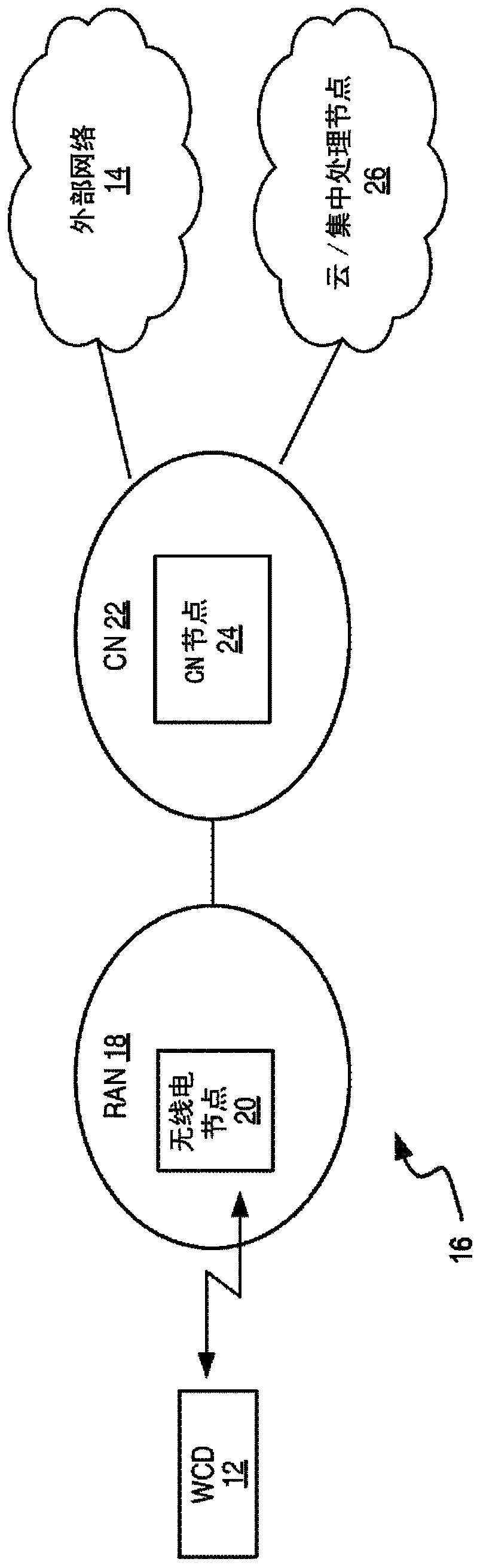
[0037] figure 2One embodiment of a wireless communication network 16 ("network 16") is shown. Network 16 provides one or more communication services to wireless communication device 12 ("device 12"), such as by communicatively coupling device 12 to one or more external networks 14, such as the Internet or other packet data network PDN. The network 16 includes a radio access network RAN ​​18 . The RAN 18 includes one or more radio network nodes 20, which may be referred to as base stations, access points, transmission points, and the like. The core network CN 22 provides eg mobility management and packet routing for the device 12, and includes one or more CN nodes 24, such as packet networks, mobility management entities, authentication servers, and the like. Network 16 may also include or be associated with one or more cloud-based or centralized processing nodes that provide processing services for various functions within network 16 .

[0038] The diagram should be understoo


PUM


Abstract

Methods and apparatuses disclosed herein enable the use of Demodulation Reference Signal, DMRS, sequences that are numbered relative to an overall system bandwidth (30), while simultaneously enablingwireless communication devices (12) to determine the DRMS sequence elements mapped to their scheduled bandwidths (36) within the system bandwidth (30). Advantageously, the wireless communication devices (12) need not know the system bandwidth (30), or even be aware of where their scheduled bandwidths (36) reside within the system bandwidth (30).

Description


Claims


Application Information

Patent Timeline
Owner TELEFON AB LM ERICSSON (PUBL)
Why Eureka
Try Eureka