Electric charging system and method

a charging system and charging method technology, applied in the direction of electric energy management, process and machine control, climate sustainability, etc., to achieve the effect of preventing inrush curren

Active Publication Date: 2020-06-18
SIEMENS ENERGY AS
View PDF0 Cites 14 Cited by
  • Summary
  • Abstract
  • Description
  • Claims
  • Application Information

AI Technical Summary

Benefits of technology

The technical effect of this patented system is that it uses an onboard grid control unit (GCCU) with two components: one for converting power from the main battery into electricity, while another component helps to protect the batteries from damage caused by sudden surges in electrical currents.

Problems solved by technology

The technical problem discussed in this patent text is how to efficiently charge electric vehicles (EVs) battery packs while also being able to use their own power source for long periods without causing issues such as interruptions caused by the lack of strong power grids nearer the EV's location.

Method used


Image

  • Electric charging system and method
  • Electric charging system and method
  • Electric charging system and method

Examples


Embodiment Construction

[0041]There are a number of different end users of electrical energy which may need to recharge at the end of a journey, such as vessels, aircraft or vehicles. The examples given herein are for vessels, but the invention is not limited to these and is equally applicable to electrically powered aircraft or electrically powered vehicles.

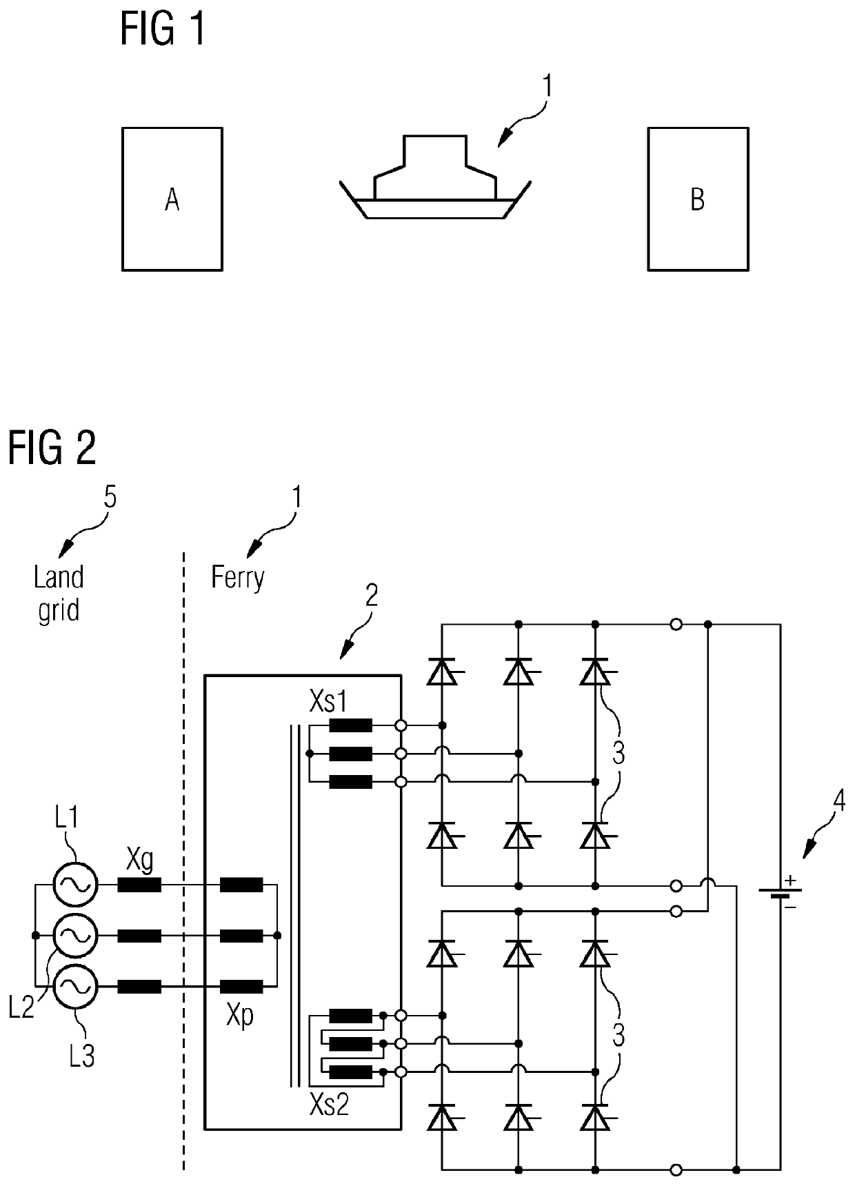
[0042]A typical situation for an electrically powered vessel with stored energy is shown in FIG. 1. A vessel, for example a ferry 1, running between ports with charging stations A, B at each port, charges up at a charging station A, before setting off on its journey. At station B the vessel recharges, then returns to its starting point and recharges again at station A. In the case of a vessel on a multi-stage journey, there may be several more ports, each with its own charging station, that are visited before returning to its home port. When docked at each port, the ferry connects to a supply, typically a shore based AC supply to charge the batteries read


PUM


Abstract

An electric charging system for a vessel, vehicle, or aircraft includes one or more energy storage modules on the vessel, vehicle, or aircraft; a pulse rectifier; a converter; and a voltage control transformer. The one or more energy storage modules are connected to outputs of the pulse rectifier. The voltage control transformer is connected to inputs of the pulse rectifier. The voltage control transformer includes a serial transformer having a plurality of pairs of transformer windings, connected together in series, one winding of each pair being adapted to be connected between the pulse rectifier and an input from an energy source and the other winding is connected to the converter.

Description


Claims


Application Information

Patent Timeline
Owner SIEMENS ENERGY AS
Why Eureka
Try Eureka