Camera for a motor vehicle and motor vehicle

A technology for motor vehicles and cameras, applied in vehicle parts, vehicle connectors, transportation and packaging, etc., can solve problems such as unfavorable and poor electromagnetic compatibility, and achieve the effect of high electromagnetic compatibility

Inactive Publication Date: 2017-08-29
CONNAUGHT ELECTRONICS
View PDF10 Cites 0 Cited by
  • Summary
  • Abstract
  • Description
  • Claims
  • Application Information

AI Technical Summary

Problems solved by technology

Poor Electromagnetic Compatibility (EMV) in existing technologies is disadvantageous

Method used


Image

  • Camera for a motor vehicle and motor vehicle
  • Camera for a motor vehicle and motor vehicle
  • Camera for a motor vehicle and motor vehicle

Examples


Embodiment Construction

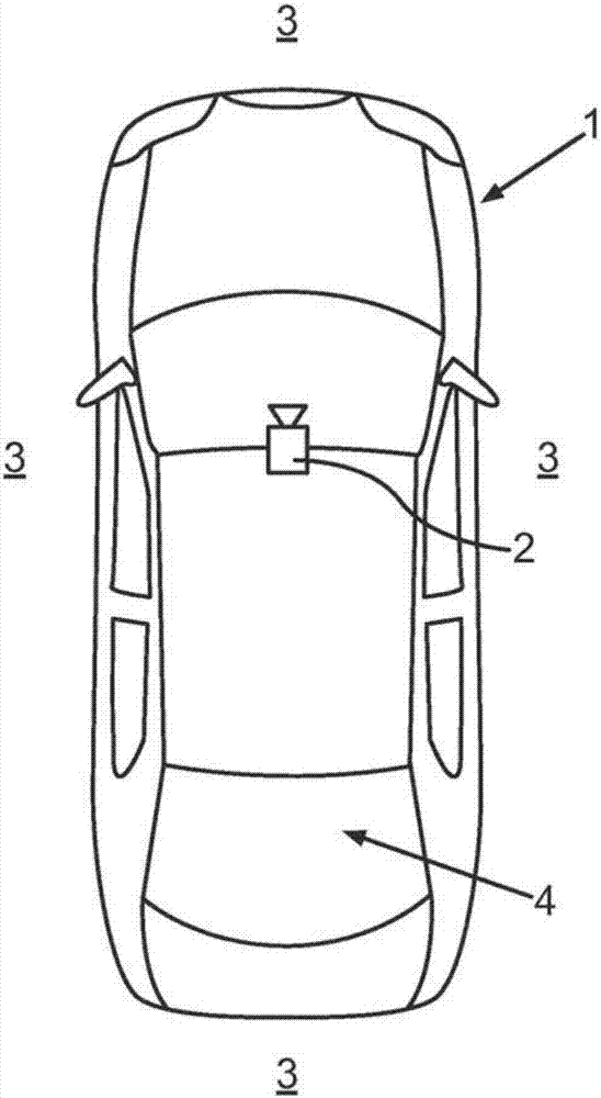
[0029] exist figure 1 , schematically shows a plan view of a motor vehicle 1 with a camera 2 according to an embodiment of the invention. The arrangement of the camera 2 on the motor vehicle 1 is arbitrary, however preferably such that the surrounding area 3 of the motor vehicle 1 and / or the interior area 4 of the motor vehicle 1 can be captured.

[0030] The motor vehicle 1 may also comprise a plurality of such cameras 2 .

[0031] Camera 2 may be a CMOS camera, or a CCD camera, or any image capture device.

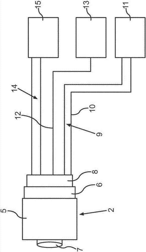
[0032] figure 2 A camera 2 is shown schematically. In the embodiment, the camera 2 includes a casing 5 , a rear cover 6 , a lens 7 and a connection part 8 . The camera 2 is connected to the motor vehicle 1 via a connection part 8 . The current line 9 leads via a connection part 8 to a fuse box 11 of the motor vehicle 1 . In addition, a test line 10 is connected from the connector part 8 to the fuse box 11 .

[0033] Further, a communication bus line 12 connects t...


PUM


Abstract

The invention relates to a camera (2) for a motor vehicle (1), which includes a printed circuit board (16), on which a current connector (29) and a communication bus connector (30) and a video interface connector (31) each for connecting to the motor vehicle (1) are disposed, wherein the video interface connector (31) is connected to a capacitor (25) and a parallel-to-serial converter (26), wherein the video interface connector (31) and / or the capacitor (25) and / or the parallel-to-serial converter (26) are surrounded by a device (32) shielding electromagnetic radiation.

Description

technical field [0001] The invention relates to a camera for a motor vehicle comprising a printed circuit board on which a current connector, a communication bus connector and a video interface connector are respectively arranged for connection to the motor vehicle. The video interface connector connects to the capacitor and the parallel-to-serial converter. Furthermore, the invention relates to a motor vehicle having at least one camera. Background technique [0002] Cameras for motor vehicles are known in the prior art. Thus, most of these cameras have electrical connectors, communication bus connectors, and video interface connectors. Current connectors are commonly used to connect the camera to the power supply of the motor vehicle. The communication bus link may eg be a CAN (Control Area Network) bus. An LVDS (Low Voltage Differential Signaling) bus is commonly used as a video interface connector. Further, the camera usually includes a CCD (Charge Coupled Device) s...

Claims


Application Information

Patent Timeline
IPC IPC(8): H01R13/658H04N5/225H05K1/02H01R13/66H05K1/14
CPCH01R13/658H05K1/0218H01R2201/26H01R13/6625H05K1/144H05K2201/10121H05K2201/042H05K2201/0715H05K1/0231H04N23/57H04N23/00H01R13/66H05K1/14
Inventor M.O.科尔曼
Owner CONNAUGHT ELECTRONICS
Why Eureka
Try Eureka