Transnasal high-flow oxygen therapy device

A high-flow, oxygen therapy technology, applied in the field of oxygen therapy instruments, can solve the problems of difficulty in adjusting the height of the airway, poor telescopic stability of the bracket rod, and poor clamping stability of the airway, so as to improve convenience and stability. and flexibility, the effect of increasing convenience

Active Publication Date: 2019-09-06
潘建伽
View PDF6 Cites 3 Cited by
  • Summary
  • Abstract
  • Description
  • Claims
  • Application Information

AI Technical Summary

Problems solved by technology

[0002] Oxygen Therapy Apparatus refers to all kinds of hypoxic treatment instruments. Inhaling high-concentration oxygen can increase the amount of dissolved oxygen in plasma, which can improve the oxygen supply of tissues. The high-flow air-oxygen mixer provides precise oxygen concentration and high-flow mixed gas. After being fully heated and humidified, it is delivered to the p

Method used


Image

  • Transnasal high-flow oxygen therapy device
  • Transnasal high-flow oxygen therapy device
  • Transnasal high-flow oxygen therapy device

Examples


Embodiment

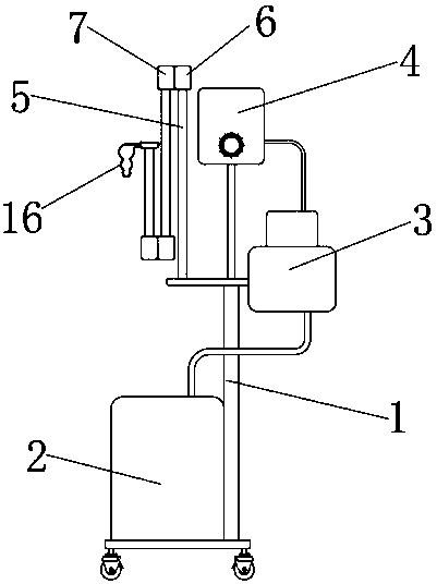
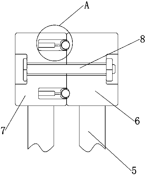
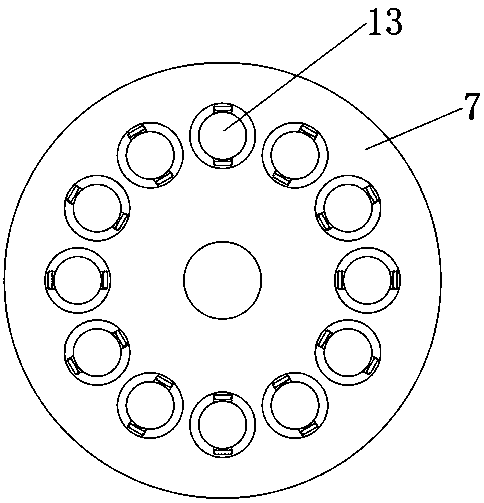
[0025] see Figure 1-7 , the present invention provides the following technical solutions: a nasal high-flow oxygen therapy device, comprising a bracket 1, an air compressor 2, a humidification water tank 3 and an air mixer 4, the air compressor 2, a humidification water tank 3 and an air mixer The devices 4 are all fixed on the surface of the support 1, and the surface of the support 1 is also fixed with a bracket rod 5, and the joints of the bracket rod 5 are provided with a sub-rotation shaft 6 and a female rotation shaft 7, and there is a connection between the sub-rotation shaft 6 and the female rotation shaft 7 The surface of the bolt 8 and the female rotating shaft 7 is provided with a movable groove 9, an outer casing 10 is installed inside the movable groove 9, a compression spring 11 is installed inside the outer casing 10, and a telescopic rod 12 is installed on the outer casing 10 through the compression spring 11. One end of the telescopic rod 12 is connected with a


PUM


Abstract

The invention belongs to the technical field of oxygen therapy instruments and particularly relates to a transnasal high-flow oxygen therapy device. The transnasal high-flow oxygen therapy device comprises a support, an air compressor, a humidifying water tank and an air mixer and is characterized in that the air compressor, the humidifying water tank and the air mixer are fixed onto the surface of the support, a bracket rod is further fixed to the surface of the support, a child rotary shaft and a mother rotary shaft are arranged at the joints of the bracket rod, a bolt is connected between the child rotary shaft and the mother rotary shaft, and a moving groove is formed in the surface of the mother rotary shaft; the joints of the bracket rod are connected through the child rotary shaft and the mother rotary shaft, the child rotary shaft and the mother rotary shaft are limited through the moving groove, an outer sleeve, a compression spring, a telescopic rod, a positioning ball and apositioning groove, the joint rotation convenience of the mother rotary shaft is increased, one end of the telescopic rod is movably mounted inside the outer sleeve through the compression spring, thepositioning ball rotatably connected to the other end of the telescopic rod is mounted inside the positioning groove, and the connecting stability of the child rotary shaft and the mother rotary shaft is increased.

Description


Claims


Application Information

Patent Timeline
Owner 潘建伽
Why Eureka
Try Eureka