Method, device and system for obtaining airspace filter parameter matrix

A technology of spatial filter and parameter matrix, which is applied in the field of data processing, can solve problems such as the inability to ensure the short spacing of the microphone array, and the inability to obtain the optimal beamforming spatial filter parameter matrix, etc., to achieve the effects of noise suppression and voice enhancement

Active Publication Date: 2019-09-06
MOBVOI INFORMATION TECH CO LTD
View PDF10 Cites 0 Cited by
  • Summary
  • Abstract
  • Description
  • Claims
  • Application Information

AI Technical Summary

Benefits of technology

This technology allows for better control over how sounds are transmitted through different media such as loudspeakers or headsets. It uses specific parameters based on factors like distance between speakers (the size) and angles from them to improve signal quality by focusing signals towards certain parts within the listener's body while reducing noise outside those areas.

Problems solved by technology

Technics: The patented technology described for improving signal processing involves controlling the timing delays associated with each loudspeaker's signals before they enter into another type called beamformer (BF). By doing this, noise interference caused by multiple sources may be reduced without sacrificing their ability to accurately capture specific audio content. Additionally, when trying to improve voice quality, filters have been developed specifically designed based on factors like frequency response characteristics and listener preferences. These techniques help reduce unwanted background noises during listening experiences.

Method used


Image

  • Method, device and system for obtaining airspace filter parameter matrix
  • Method, device and system for obtaining airspace filter parameter matrix
  • Method, device and system for obtaining airspace filter parameter matrix

Examples


Embodiment Construction

[0040] The implementation mode of the present invention is illustrated by specific specific examples below, and those who are familiar with this technology can easily understand other advantages and effects of the present invention from the contents disclosed in this description. Obviously, the described embodiments are a part of the present invention. , but not all examples. Based on the embodiments of the present invention, all other embodiments obtained by persons of ordinary skill in the art without making creative efforts belong to the protection scope of the present invention.

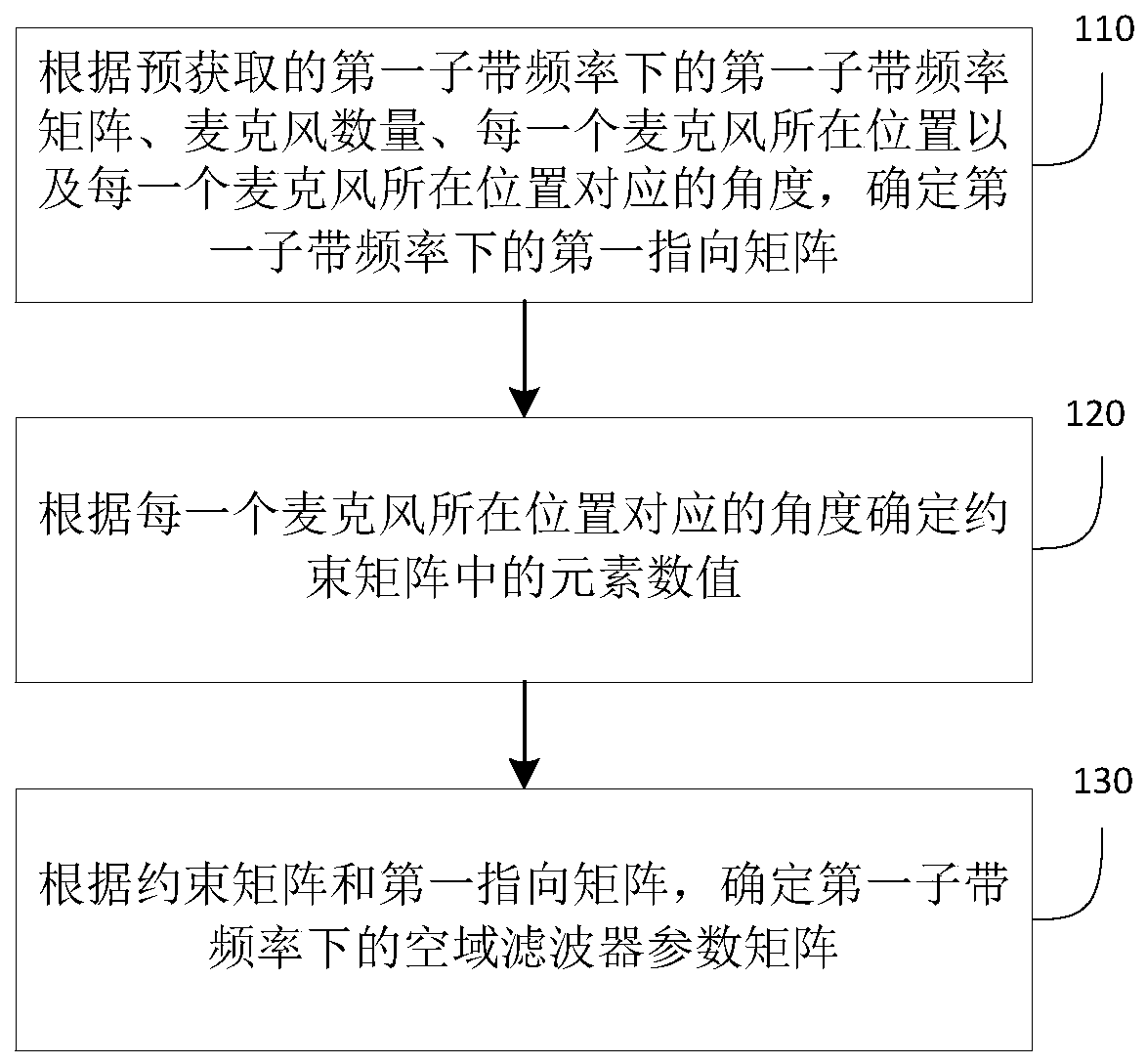
[0041] Embodiment 1 of the present invention provides a method for obtaining a parameter matrix of a spatial domain filter, specifically as figure 1 As shown, the method can be applied to headsets, VR glasses, or similar electronic devices that require a multi-microphone array for wearable devices that have strict requirements on volume. The method includes:

[0042]Step 110: Determine the first o


PUM


Abstract

The embodiments of the invention relate to the technical field of data processing and particularly disclose a method, device and system for obtaining an airspace filter parameter matrix. The method comprises the steps that a first pointing matrix under first sub-band frequency is determined according to a pre-obtained first sub-band frequency matrix under the first sub-band frequency, the pre-obtained number of microphones, the pre-obtained position where each microphone is located, and the pre-obtained angle corresponding to the position where each microphone is located; numerical values of elements in a constraint matrix are determined according to the angle corresponding to the position where each microphone is located, wherein the number of the elements in the constraint matrix is thesame as that of the microphones; and the airspace filter parameter matrix under the first sub-band frequency is determined according to the constraint matrix and the first pointing matrix. In this way, it can be further ensured that a microphone array receives sound in the preset direction while small-interval arrangement of the microphone array is met, and voice enhancement is realized.

Description


Claims


Application Information

Patent Timeline
Owner MOBVOI INFORMATION TECH CO LTD
Why Eureka
Try Eureka