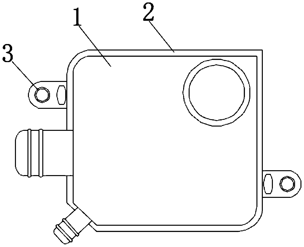
Novel breathing apparatus

A respirator, a new type of technology, applied in the direction of machines/engines, engine components, mechanical equipment, etc., can solve problems such as inconvenience, and achieve the effect of convenient installation

Active Publication Date: 2019-09-27
YANCHENG JIANGDONG GASOLINE ENGINE MFG +1
View PDF16 Cites 1 Cited by
  • Summary
  • Abstract
  • Description
  • Claims
  • Application Information

AI Technical Summary

Problems solved by technology

[0003] When the existing respirator is installed, the threaded connecting plate of the welding machine on the respirator base is generally connected with the crankcase thread, but the respirator needs to be replaced after a long period of use, and the current respirator When the respirator is replaced, the staff needs to remove the

Method used


Image

  • Novel breathing apparatus
  • Novel breathing apparatus
  • Novel breathing apparatus

Examples


Embodiment Construction

[0051] A number of embodiments of the present invention will be disclosed in the following figures. For the sake of clarity, many practical details will be described together in the following description. It should be understood, however, that these practical details should not be used to limit the invention. That is, in some embodiments of the invention, these practical details are not necessary. In addition, for the sake of simplifying the drawings, some well-known and commonly used structures and components will be shown in a simple schematic manner in the drawings.

[0052] In addition, in the present invention, descriptions such as "first", "second" and so on are used for description purposes only, and do not refer to the meaning of sequence or sequence, nor are they used to limit the present invention, but are only for the purpose of distinguishing the following The components or operations described by the same technical terms are merely used, but should not be understood


PUM


Abstract

The invention discloses a novel breathing apparatus. The novel breathing apparatus comprises a breathing apparatus body, and the back of the breathing apparatus body is fixedly connected with a bottom plate; the left side, the right side, the top and the bottom of a bottom plate body are all provided with slide grooves, and inner cavities of the slide grooves are slidably connected with fixing devices; and each fixing device comprises a connection plate, and the side, away from the bottom plate, of the connection plate is provided with a threaded hole. According to the novel breathing apparatus, through structural design between the slide grooves and the bottom plate, the fixing devices can move on the peripheries of the connection plates, meanwhile, through structural design and position relation between second reset springs and pressing blocks, workers can conveniently squeeze the pressing blocks to enable two moving plates to move towards the centers of the inner cavities of the connection plates, accordingly, the two moving plates can be inserted into the slide grooves, the workers can conveniently connect the fixing devices with the connection plates together or disassemble the fixing devices from the connection plates, and the novel breathing apparatus can achieve the purpose of being connected with different automobile crankcases.

Description


Claims


Application Information

Patent Timeline
Owner YANCHENG JIANGDONG GASOLINE ENGINE MFG
Why Eureka
Try Eureka