Dynamic visual displacement measurement method based on automatic encoder

An automatic encoder and displacement measurement technology, which is applied in the direction of measuring devices, instruments, image data processing, etc., can solve the problems of lack of characteristic information and uncommon problems

Pending Publication Date: 2019-10-15
FUZHOU UNIV
View PDF6 Cites 0 Cited by
  • Summary
  • Abstract
  • Description
  • Claims
  • Application Information

AI Technical Summary

Benefits of technology

This technology allows for better accuracy than previous methods that only use specific parts or markers placed at certain locations within an image frame. It uses both automatic coding techniques (such as autoencoders) and specialized algorithms like motion estimation to calculate the necessary movement data from images captured through cameras mounted inside vehicles' cabins. These technical improvements result in improved vehicle safety performance during autonomous driving operations.

Problems solved by technology

This patented technical problem addressed in this patents relates to improving the efficiency and precision of measuring displacements without relying solely upon human observation or subjective judgment. Current techniques have limitations due to their high costs and complexity caused by changing physical properties of cables with complex geometry. There also exist challenges for accurately extracting specific features associated with 6 degree of motion (DOF) measurements.

Method used


Image

  • Dynamic visual displacement measurement method based on automatic encoder
  • Dynamic visual displacement measurement method based on automatic encoder
  • Dynamic visual displacement measurement method based on automatic encoder

Examples


Embodiment Construction

[0039] The present invention will be further described below in conjunction with the accompanying drawings and embodiments.

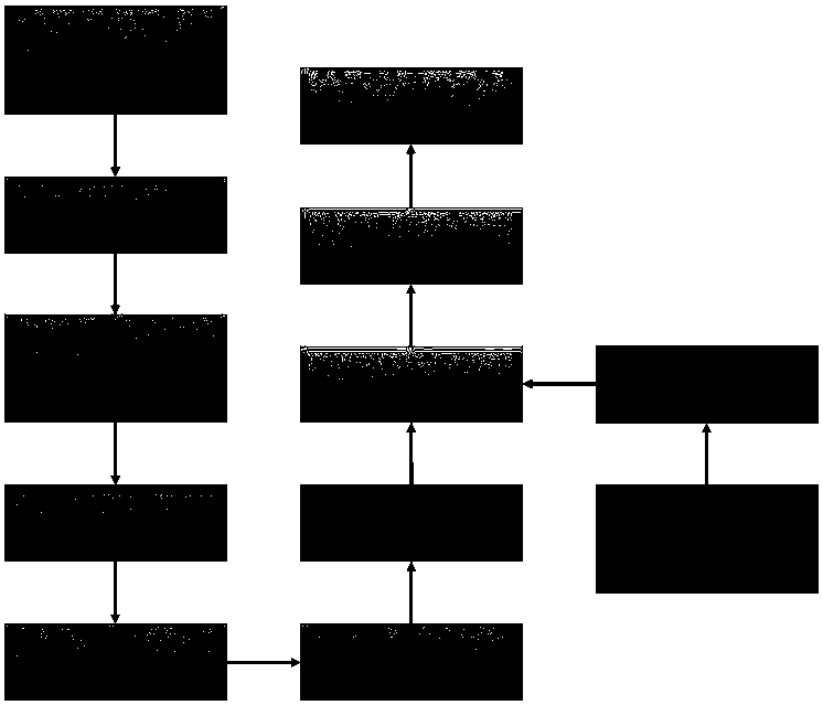
[0040] Please refer to figure 1 , the present invention provides a kind of dynamic visual displacement measurement method based on autoencoder, it is characterized in that, comprises the following steps:

[0041] Step S1: construct the feature points attached to the surface of the cylinder;

[0042] Step S2: Use the binocular camera to collect dynamic video data on the cylinder with feature points to obtain the left and right view data sets;

[0043] Step S3: extract target feature points according to the obtained left and right view data sets, and obtain image two-dimensional coordinates of feature corner points;

[0044] Step S4: Calibrate the binocular camera to obtain the internal and external parameter matrices of the binocular camera;

[0045] Step S5: According to the two-dimensional coordinates of the image of the internal and external parameter


PUM


Abstract

The invention relates to a dynamic visual displacement measurement method based on an automatic encoder. The method comprises the following steps: S1, constructing feature points attached to the surface of a cylinder; S2, performing dynamic video data acquisition on the cylinder attached with the feature points by using a binocular acquisition system to obtain left and right view data sets; S3, extracting target feature points according to the obtained left and right view data sets, and obtaining image two-dimensional coordinates of the obtained feature corner points; S4, performing calibration processing on the binocular acquisition system to obtain an internal parameter matrix and an external parameter matrix of the binocular camera; S5, reconstructing a three-dimensional world coordinate set of the feature points according to the obtained internal and external parameter matrixes of the binocular camera and the image two-dimensional coordinates of the feature angular points; and S6,performing cylinder fitting by utilizing the three-dimensional world coordinate set of the feature points according to the cylinder structure, and performing calculation to obtain a rotating Euler angle. The displacement and rotation angle information of the target in the dynamic video can be calculated by collecting the feature point information of the target object, and the target object does not need to be directly contacted.

Description


Claims


Application Information

Patent Timeline
Owner FUZHOU UNIV
Why Eureka
Try Eureka